Entity Relationship Diagram Symbols

ERD symbols used for professional ERD drawing are collected in libraries from the Entity-Relationship Diagram (ERD) solution for ConceptDraw DIAGRAM.
Software development with ConceptDraw DIAGRAM

Express-G Diagram
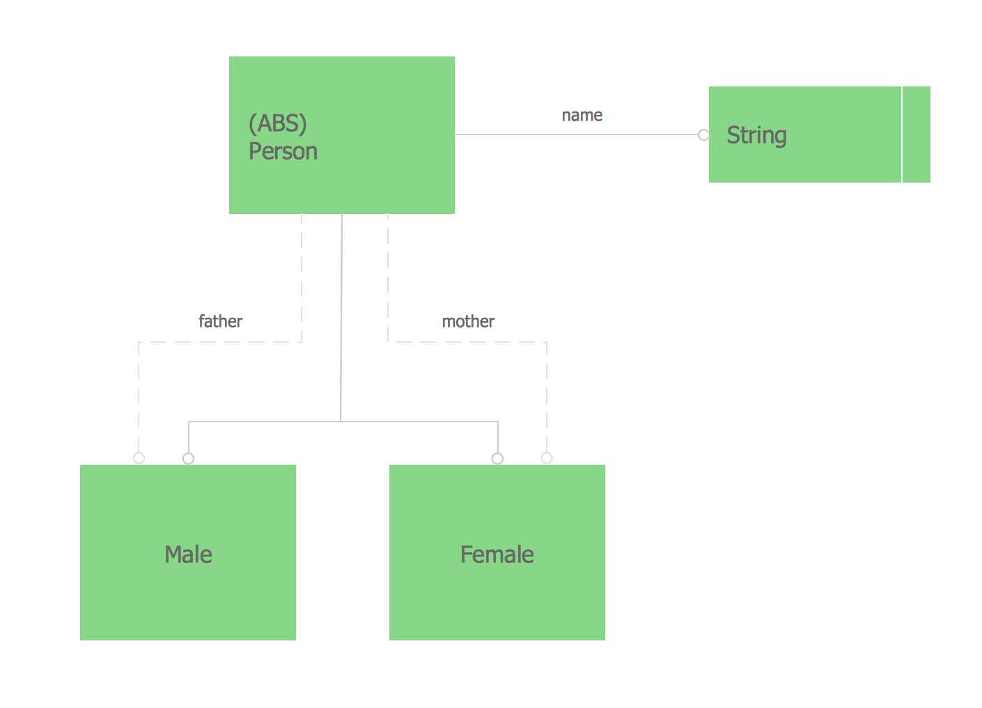
UML Diagram

Create unified modeling language (UML) diagrams with ConceptDraw.
ER Diagram Tool

Venn Diagram Examples for Problem Solving. Computer Science. Chomsky Hierarchy

The Venn diagram example below visualizes the the class of language inclusions described by the Chomsky hierarchy.
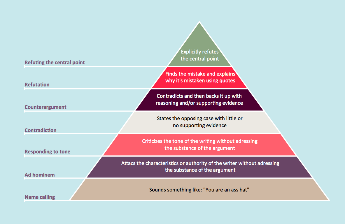
Pyramid Diagram
Data Modeling Diagram

Database Design

- Programming Language Relationship Diagram
- What Is Er And Dfd Diagram In Programming Language
- Business Process Diagrams | Entity Relationship Diagram Symbols ...
- Venn Diagram Examples for Problem Solving. Computer Science ...
- ConceptDraw PRO The best Business Drawing Software | Entity ...
- UML Diagrams with ConceptDraw PRO | UML Class Diagrams ...
- Entity- Relationship Diagram (ERD) | Event-driven Process Chain ...
- Entity Relationship Diagram Symbols | Database Flowchart Symbols ...
- Audio and Video Connectors | How to Create a Hook Up Diagram ...
- Process Flowchart | UML Notation | Entity Relationship Diagram ...
- ERD | Entity Relationship Diagrams, ERD Software for Mac and Win
- Flowchart | Basic Flowchart Symbols and Meaning
- Flowchart | Flowchart Design - Symbols, Shapes, Stencils and Icons
- Flowchart | Flow Chart Symbols
- Electrical | Electrical Drawing - Wiring and Circuits Schematics
- Flowchart | Common Flowchart Symbols
- Flowchart | Common Flowchart Symbols