Electrical Drawing Software and Electrical Symbols

Electrical Drawing Software provides the 26 stencils libraries of ready-to-use predesigned vector electrical symbols, templates and samples that make your electrical drawing quick, easy and effective.
Electrical Symbols — Transformers and Windings

26 libraries of the Electrical Engineering Solution of ConceptDraw DIAGRAM make your electrical diagramming simple, efficient, and effective. You can simply and quickly drop the ready-to-use objects from libraries into your document to create the electrical diagram.
Basic CCTV System Diagram. CCTV Network Diagram Example

This cafe electrical floor plan sample shows the outlet and switch layout.
"An electrical drawing, is a type of technical drawing that shows information about power, lighting, and communication for an engineering or architectural project. Any electrical working drawing consists of "lines, symbols, dimensions, and notations to accurately convey an engineering's design to the workers, who install the electrical system on the job".
A complete set of working drawings for the average electrical system in large projects usually consists of:
(1) A plot plan showing the building's location and outside electrical wiring.
(2) Floor plans showing the location of electrical systems on every floor.
(3) Power-riser diagrams showing panel boards.
(4) Control wiring diagrams.
(5) Schedules and other information in combination with construction drawings.
Electrical drafters prepare wiring and layout diagrams used by workers who erect, install, and repair electrical equipment and wiring in communication centers, power plants, electrical distribution systems, and buildings." [Electrical drawing. Wikipedia]
The outlet and switch layout example "Cafe electrical floor plan" was created using the ConceptDraw PRO diagramming and vector drawing software extended with the Electric and Telecom Plans solution from the Building Plans area of ConceptDraw Solution Park.
Outlet and switch layout

The vector stencils library "Switches and relays" contains 58 symbols of electrical contacts, switches, relays, circuit breakers, selectors, connectors, disconnect devices, switching circuits, current regulators, and thermostats for electrical devices.
Use these shapes for drawing electrical diagrams in the ConceptDraw PRO diagramming and vector drawing software extended with the Electrical Engineering solution from the Engineering area of ConceptDraw Solution Park.
www.conceptdraw.com/ solution-park/ engineering-electrical
Use these shapes for drawing electrical diagrams in the ConceptDraw PRO diagramming and vector drawing software extended with the Electrical Engineering solution from the Engineering area of ConceptDraw Solution Park.
www.conceptdraw.com/ solution-park/ engineering-electrical
SPST

SPDT

DPST

DPDT

Make contact

Break contact

Two way contact

Passing make-contact

Spring return

Stay put

Limit switch

Circuit breaker

Spring return 2

Spring return 3

Limit switch n/o

Limit switch n/c

2 position switch

3 position switch

4 position switch

Manual switch

Pushbutton make

Pushbutton break

Pushbutton 2-circuit

Selector switch

Shorting selector

Proximity limit switch

Time delay make

Time delay break

Time delay make 2

Time delay break 2

Safety interlock

Flow actuated

Liquid level actuated

Liquid level actuated 2

Gas flow actuated

Pressure actuated

Temperature actuated

Thermostat

Temperature switch

Inertia switch

Mercury switch

Mercury switch 2

Fuse

Switch disconnector

Isolator

Change-over contact

Relay contacts

Relay coil

Pilot light

Pilot light, push-to-test

Relay, alternating-current

Relay, magnetically polarized

Relay, slow-operate

Relay, slow-release

Relay

Relay, high speed

Relay, mechanically latched

Relay, permanent

The vector stencils library "Switches" contains 25 symbols of electrical switches.
Use it for drawing electrical design floor and building plans, devices and equipment layouts in the ConceptDraw PRO diagramming and vector drawing software.
The vector stencils library "Switches" is included in the Electric and Telecom Plans solution from the Building Plans area of ConceptDraw Solution Park.
Single pole switch

Switch control

Dimmer switch

Dimmer switch 2

Double Pole Switch

Three-way switch

Four-way switch

Automatic door switch

Electrolier switch

Key operated switch

Switch and pilot lamp

Key operated switch with pilot light

Circuit breaker

Weatherproof circuit breaker

Momentary contact switch

Remote control switch

Weatherproof switch

Fused switch

Weatherproof fused switch

Switch with timer

Glow switch toggle

Horizontally mounted switch

Low voltage master switch

Low voltage switch

Single pole double throw switch

Swim Lane Flowchart Symbols

The vector stencils library "Terminals and connectors" contains 43 element symbols of terminals, connectors, plugs, polarized connectors, jacks, coaxial cables, and conductors.
Use it for drawing the wiring diagrams, electrical layouts, electronic schematics, and circuit diagrams in the ConceptDraw PRO diagramming and vector drawing software extended with the Electrical Engineering solution from the Engineering area of ConceptDraw Solution Park.
www.conceptdraw.com/ solution-park/ engineering-electrical
2-conductor jack

2-conductor plug

2-conductor jack 2

2-conductor plug 2

Normalled jacks

Normalled jack

Outside conductor coaxial

Center conductor coaxial

Large D connector

Small D connector

C header connector

Normalled jacks

Сontact, male

Сontact, female

Сontact, male 2

Сontact, female 2

Adapter, male - male

Adapter, male - male

Circuit terminal

Terminal board

Cable termination, complete

Cable termination, single-line

Cable termination, single-line 2

Shielded jack

Shielded plug

Coaxial jack

Coaxial plug

2-conductor, male

2-conductor, female

2-conductor, male 2

2-conductor, female 2

2-conductor, male 3

2-conductor, female 3

3-conductor, male

3-conductor, female

3-conductor, male 2

3-conductor, female 2

3-conductor, male 3

3-conductor, female 3

3-conductor, male 4

3-conductor, female 4

3-conductor, male 5

3-conductor, female 5

The vector stencils library "Transmission paths" contains 43 symbols of power transmission paths, electronic circuits, bus connectors and elbows, terminals, junctions, and concentrators.
Use it to annotate electrical diagrams, electronic schematics and circuit diagrams.
"A physical medium in data communications is the transmission path over which a signal propagates.
Many transmission media are used as communications channel.
For telecommunications purposes in the United States, Federal Standard 1037C, transmission media are classified as one of the following:
(1) Guided (or bounded) - waves are guided along a solid medium such as a transmission line.
(2) Wireless (or unguided) - transmission and reception are achieved by means of an antenna.
One of the most common physical medias used in networking is copper wire. Copper wire to carry signals to long distances using relatively low amounts of power. The unshielded twisted pair (UTP) is eight strands of copper wire, organized into four pairs.
Another example of a physical medium is optical fiber, which has emerged as the most commonly used transmission medium for long-distance communications. Optical fiber is a thin strand of glass that guides light along its length.
Multimode and single mode are two types of commonly used optical fiber. Multimode fiber uses LEDs as the light source and can carry signals over shorter distances, about 2 kilometers. Single mode can carry signals over distances of tens of miles.
Wireless media may carry surface waves or skywaves, either longitudinally or transversely, and are so classified.
In both communications, communication is in the form of electromagnetic waves. With guided transmission media, the waves are guided along a physical path; examples of guided media include phone lines, twisted pair cables, coaxial cables, and optical fibers. Unguided transmission media are methods that allow the transmission of data without the use of physical means to define the path it takes. Examples of this include microwave, radio or infrared. Unguided media provide a means for transmitting electromagnetic waves but do not guide them; examples are propagation through air, vacuum and seawater.
The term direct link is used to refer to the transmission path between two devices in which signals propagate directly from transmitters to receivers with no intermediate devices, other than amplifiers or repeaters used to increase signal strength. This term can apply to both guided and unguided media.
A transmission may be simplex, half-duplex, or full-duplex.
In simplex transmission, signals are transmitted in only one direction; one station is a transmitter and the other is the receiver. In the half-duplex operation, both stations may transmit, but only one at a time. In full duplex operation, both stations may transmit simultaneously. In the latter case, the medium is carrying signals in both directions at same time." [Transmission medium. Wikipedia]
The shapes example "Design elements - Transmission paths" was drawn using the ConceptDraw PRO diagramming and vector drawing software extended with the Electrical Engineering solution from the Engineering area of ConceptDraw Solution Park.
Transmission path symbols

Network Diagram Software. LAN Network Diagrams. Physical Office Network Diagrams


The logic gate diagram example "2-bit ALU" was redesigned from the Wikimedia Commons file: 2-bit ALU.svg.
[commons.wikimedia.org/ wiki/ File:2-bit_ ALU.svg]
This file is licensed under the Creative Commons Attribution-Share Alike 3.0 Unported license. [creativecommons.org/ licenses/ by-sa/ 3.0/ deed.en]
"In digital electronics, an arithmetic and logic unit (ALU) is a digital circuit that performs integer arithmetic and logical operations. The ALU is a fundamental building block of the central processing unit of a computer, and even the simplest microprocessors contain one for purposes such as maintaining timers. The processors found inside modern CPUs and graphics processing units (GPUs) accommodate very powerful and very complex ALUs; a single component may contain a number of ALUs. ...
Most of a processor's operations are performed by one or more ALUs. An ALU loads data from input registers. Then an external control unit tells the ALU what operation to perform on that data, and then the ALU stores its result into an output register. The control unit is responsible for moving the processed data between these registers, ALU and memory." [Arithmetic logic unit. Wikipedia]
The logic gate diagram example "2-bit ALU" was created using the ConceptDraw PRO diagramming and vector drawing software extended with the Electrical Engineering solution from the Engineering area of ConceptDraw Solution Park.
Logic gate diagram

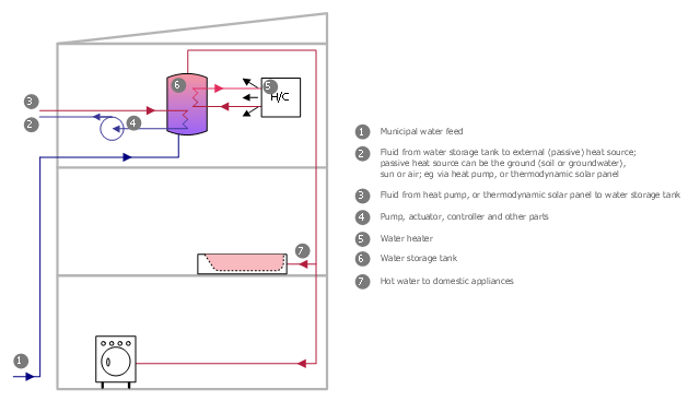
This plumbing and piping plan sample was designed on the base of the Wikimedia Commons file: Active Indirect Water Heater Diagram.svg.
[commons.wikimedia.org/ wiki/ File:Active_ Indirect_ Water_ Heater_ Diagram.svg]
This file is licensed under the Creative Commons Attribution-Share Alike 3.0 Unported license. [creativecommons.org/ licenses/ by-sa/ 3.0/ deed.en]
"Water heating is a thermodynamic process that uses an energy source to heat water above its initial temperature. Typical domestic uses of hot water include cooking, cleaning, bathing, and space heating. In industry, hot water and water heated to steam have many uses.
Domestically, water is traditionally heated in vessels known as water heaters, kettles, cauldrons, pots, or coppers. These metal vessels that heat a batch of water do not produce a continual supply of heated water at a preset temperature. Rarely, hot water occurs naturally, usually from natural hot springs. The temperature varies based on the consumption rate, becoming cooler as flow increases.
Appliances that provide a continual supply of hot water are called water heaters, hot water heaters, hot water tanks, boilers, heat exchangers, geysers, or calorifiers. These names depend on region, and whether they heat potable or non-potable water, are in domestic or industrial use, and their energy source. In domestic installations, potable water heated for uses other than space heating is also called domestic hot water (DHW).
Fossil fuels (natural gas, liquefied petroleum gas, oil), or solid fuels are commonly used for heating water. These may be consumed directly or may produce electricity that, in turn, heats water. Electricity to heat water may also come from any other electrical source, such as nuclear power or renewable energy. Alternative energy such as solar energy, heat pumps, hot water heat recycling, and geothermal heating can also heat water, often in combination with backup systems powered by fossil fuels or electricity." [Water heating. Wikipedia]
The plumbing plan example "Active indirect water heater diagram" was created using the ConceptDraw PRO diagramming and vector drawing software extended with the Plumbing and Piping Plans solution from the Building Plans area of ConceptDraw Solution Park.
Plumbing and piping plan
Local area network (LAN). Computer and Network Examples
 diagram")
ConceptDraw - Perfect Network Diagramming Software with examples of LAN Diagrams. ConceptDraw Network Diagram is ideal for network engineers and network designers who need to draw Local Area Network diagrams.
The vector stencils library "LDAP" contains 20 symbols of Lightweight Directory Access Protocol (LDAP) elements for drawing the LDAP Directory Services network structure diagrams.
"The Lightweight Directory Access Protocol (LDAP) is an open, vendor-neutral, industry standard application protocol for accessing and maintaining distributed directory information services over an Internet Protocol (IP) network. Directory services play an important role in developing intranet and Internet applications by allowing the sharing of information about users, systems, networks, services, and applications throughout the network. As examples, directory services may provide any organized set of records, often with a hierarchical structure, such as a corporate email directory. Similarly, a telephone directory is a list of subscribers with an address and a phone number.
LDAP is specified in a series of Internet Engineering Task Force (IETF) Standard Track publications called Request for Comments (RFCs), using the description language ASN.1. The latest specification is Version 3, published as RFC 4511. ...
A common usage of LDAP is to provide a "single sign on" where one password for a user is shared between many services, such as applying a company login code to web pages (so that staff log in only once to company computers, and then are automatically logged into the company intranet).
LDAP is based on a simpler subset of the standards contained within the X.500 standard. Because of this relationship, LDAP is sometimes called X.500-lite." [Lightweight Directory Access Protocol. Wikipedia]
The symbols example "LDAP - Vector stencils library" was created using the ConceptDraw PRO diagramming and vector drawing software extended with the Active Directory Diagrams solution from the Computer and Networks area of ConceptDraw Solution Park.
www.conceptdraw.com/ solution-park/ active-directory-diagrams
Country

Organization
Organizational unit
Generic object

Locality

Alias

Person

InetOrgPerson

Organizational person

Residential person

Organizational role

Group of names

Group of unique names

Device
cRL distribution point
dSA
dmd
Application process

Application entity

Unknown

- Electrical Drawing Software and Electrical Symbols | Network ...
- Electrical Drawing Software and Electrical Symbols | Swim Lane ...
- Electrical Single Line Diagram Of A Restaurant
- How To use House Electrical Plan Software | Design elements ...
- How To Drwaw Electrical Single Line Diagram With Adobe Illustrator
- Electrical Single Line Diagram Of Floor
- Substation Single Line Diagram Symbols
- Single Line Diagram Of Electrical Power System Of A House
- Basic Hydraulic System Single Line Diagram
- Electrical Drawing Software and Electrical Symbols | Computer ...
- Software For Drawing Electrical Circuit For Android
- Single Line Diagram Of Hotel
- Electrical Single Line Diagram For House
- Android User Interface | 2-bit ALU - Logic gate diagram | Electrical ...
- Single Line Diagram Electriccal Network Android
- Building Drawing Software for Designing Plumbing | Line Graph ...
- Single Line Diagram Of Electrical Residential
- Electrical Single Line Drawing Symbols
- How To Draw Hvac Single Line Diagram
- Power socket outlet layout | Electrical Layout Definition
- ERD | Entity Relationship Diagrams, ERD Software for Mac and Win
- Flowchart | Basic Flowchart Symbols and Meaning
- Flowchart | Flowchart Design - Symbols, Shapes, Stencils and Icons
- Flowchart | Flow Chart Symbols
- Electrical | Electrical Drawing - Wiring and Circuits Schematics
- Flowchart | Common Flowchart Symbols
- Flowchart | Common Flowchart Symbols