HelpDesk
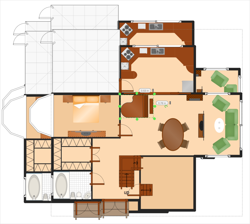
How to Resize Objects
Electrical Symbols — Terminals and Connectors

26 libraries of the Electrical Engineering Solution of ConceptDraw DIAGRAM make your electrical diagramming simple, efficient, and effective. You can simply and quickly drop the ready-to-use objects from libraries into your document to create the electrical diagram.
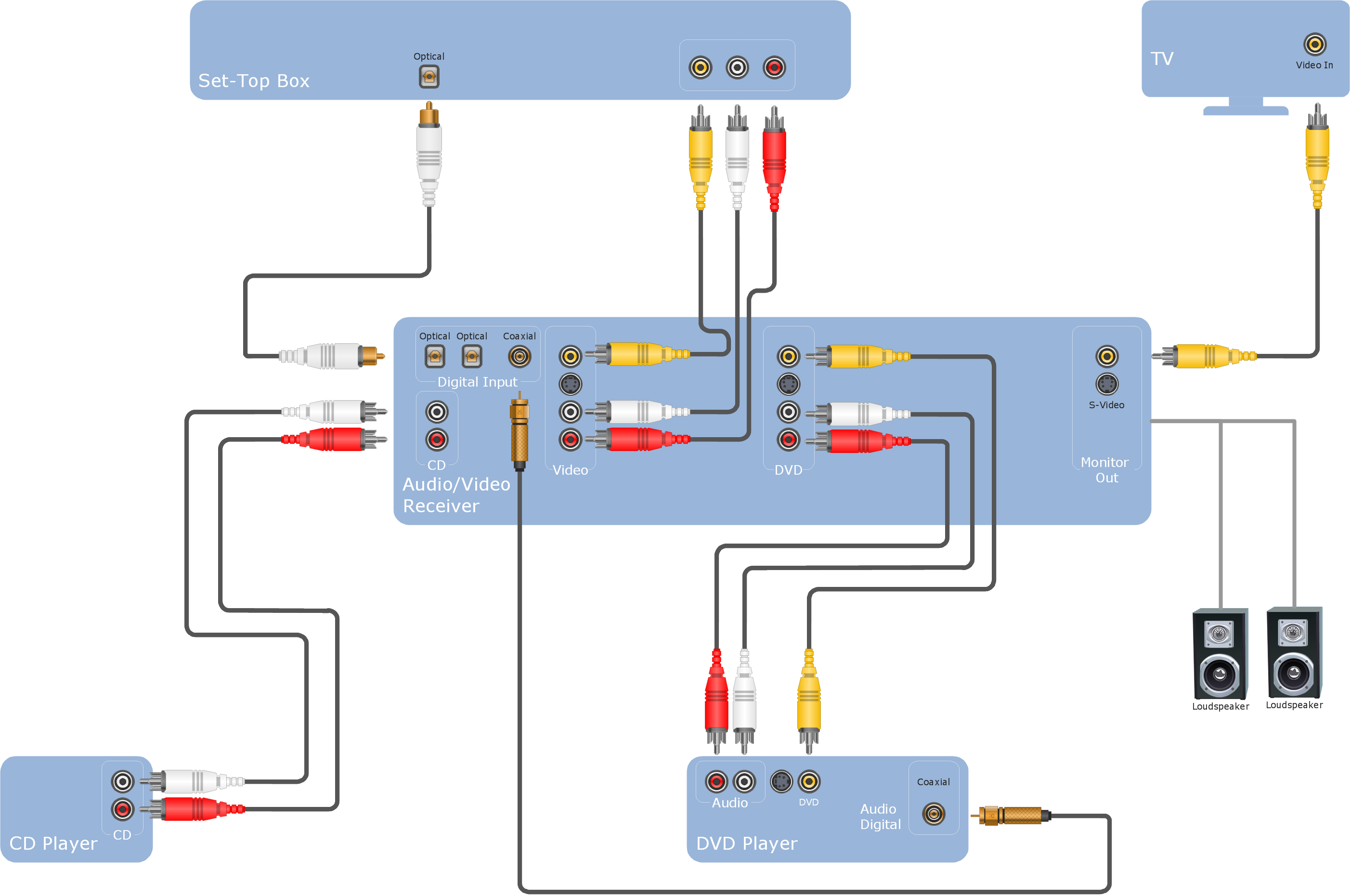
 Audio and Video Connectors
The Audio and Video Connectors solution contains a set of video connectors, audio connectors and s video connection; you will also find pre-designed objects, libraries, templates, and samples, allowing quick and easy diagramming of various configurations
Audio Visual Cables and Connectors
Wiring Diagrams with ConceptDraw DIAGRAM

Audio Connectors

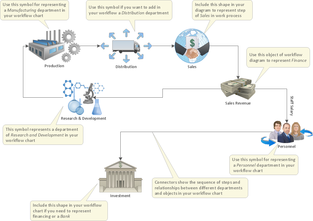
How to Draw an Effective Workflow
Audio & Video Connections
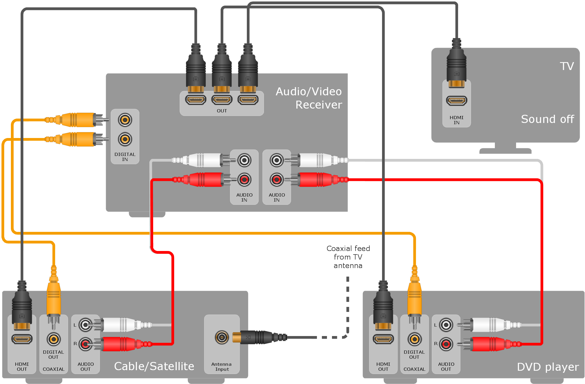
Standard Universal Audio & Video Connection Types

How to Make Audio and Video Connections

- Draw The Diagram Layout Cable Coaxial
- Audio Visual Connectors Types | Audio and Video Connections ...
- Av Line Drawing Software
- Av Connection Diagrams
- Network wiring cable . Computer and Network Examples | Network ...
- Av Schematic Diagram
- Network Diagramming Software for Design Rack Diagrams | Design ...
- How To use House Electrical Plan Software | Audio and Video ...
- Audio Visual Connectors Types | Audio and Video Connectors ...
- Av Design Diagram Drawing Software Free For Mac Os
- ERD | Entity Relationship Diagrams, ERD Software for Mac and Win
- Flowchart | Basic Flowchart Symbols and Meaning
- Flowchart | Flowchart Design - Symbols, Shapes, Stencils and Icons
- Flowchart | Flow Chart Symbols
- Electrical | Electrical Drawing - Wiring and Circuits Schematics
- Flowchart | Common Flowchart Symbols
- Flowchart | Common Flowchart Symbols