Local area network (LAN). Computer and Network Examples
 diagram")

 Network Layout Floor Plans
Network Layout Floor Plans solution extends ConceptDraw DIAGRAM software functionality with powerful tools for quick and efficient documentation the network equipment and displaying its location on the professionally designed Network Layout Floor Plans. Never before creation of Network Layout Floor Plans, Network Communication Plans, Network Topologies Plans and Network Topology Maps was not so easy, convenient and fast as with predesigned templates, samples, examples and comprehensive set of vector design elements included to the Network Layout Floor Plans solution. All listed types of plans will be a good support for the future correct cabling and installation of network equipment.
Star Network Topology


Diagram of a Basic Computer Network. Computer Network Diagram Example

Mesh Network Topology Diagram

IDEF4 Standard

Metropolitan area networks (MAN). Computer and Network Examples
. Computer and Network Examples")
ERD Symbols and Meanings


Ring Network Topology

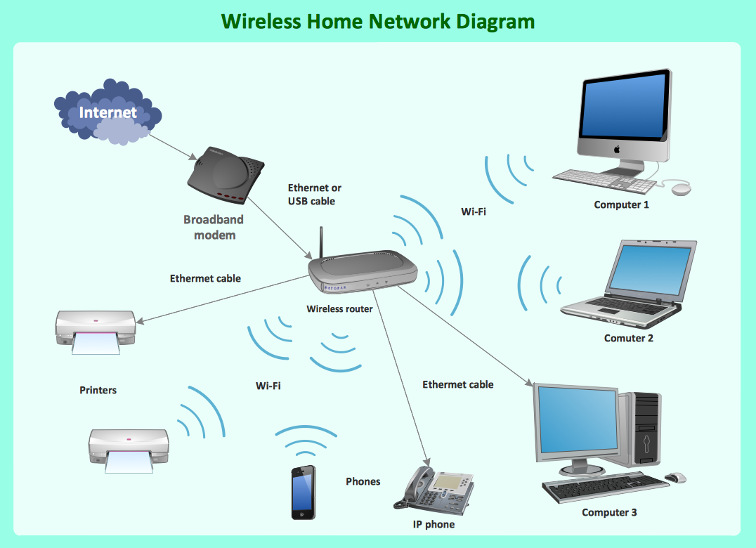
What Is a Wireless Network?
- Chemistry Drawing Software | Biology Illustration | Network Layout ...
- Wan Diagram
- Diagrams Of Lan Wan Man Networks
- With The Aid Of A Well Labelled Diagram Explain Tre Topology
- Process Flow Diagram Symbols | Electrical Drawing Software and ...
- How to Draw Chemistry Structures | Chemistry | Design elements ...
- Draw The Diagram Of Kreb Cycle
- With A Well Labeled Diagram Eplain The Types Of Information
- What Is Filtration Draw And Label A Diagram Showing Filtration
- Draw And Label A Computer System