SSADM Diagram

Financial Trade UML Use Case Diagram Example

Technical Flow Chart Example

Gantt chart examples

Create Floor Plans Easily with ConceptDraw DIAGRAM


Jacobson Use Cases Diagram

UML Sequence Diagram Example. SVG Vectored UML Diagrams Tools

Entity Relationship Diagram - ERD - Software for Design Crows Foot ER Diagrams
_Win_Mac.png)

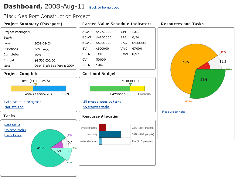
How To Create Project Report
ERD Symbols and Meanings

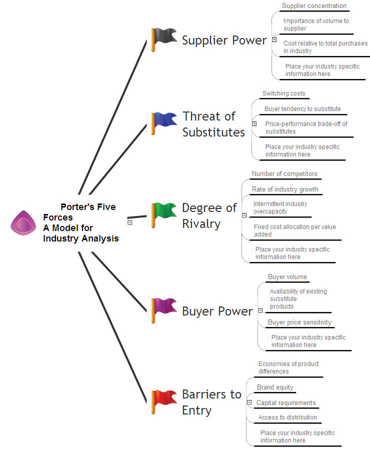
 SWOT and TOWS Matrix Diagrams
SWOT and TOWS Matrix Diagrams solution extends ConceptDraw DIAGRAM and ConceptDraw MINDMAP software with features, templates, samples and libraries of vector stencils for drawing SWOT and TOWS analysis matrices and mind maps.
Business Productivity - Marketing
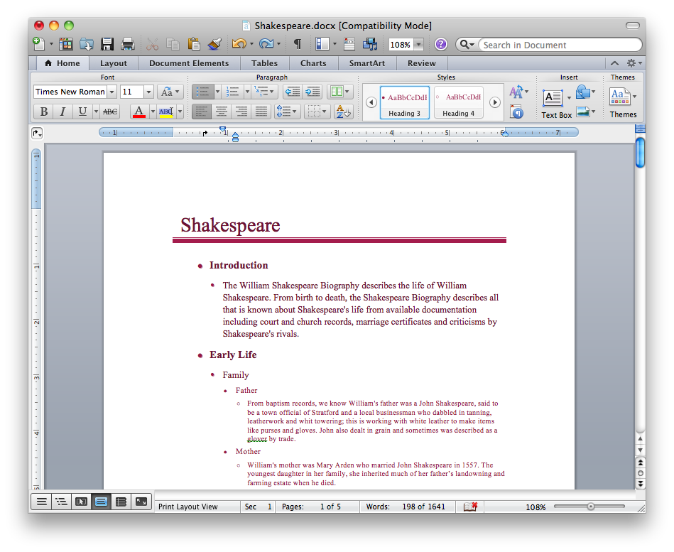
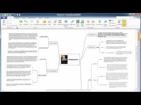
Export from ConceptDraw MINDMAP into MS Word Document
UML Diagram Visio

Electrical Symbols, Electrical Diagram Symbols

- Diagram Of Home Trade
- Procedure In Home Trade
- Create Floor Plans Easily with ConceptDraw PRO | Procedures In ...
- Showing The Diagram Of Home Trade
- Flow Chart Creator | Build a Flowchart Quickly With AutoConnect ...
- Jacobson Use Cases Diagram | Trade Store Er Diagram
- International Trade Block Diagram
- Financial Trade UML Use Case Diagram Example | SSADM ...
- Trade Store Database And Er Diagram
- Trading process diagram - Deployment flowchart | Flow Chart ...
- Jacobson Use Cases Diagram | Er Diagram Of A Trade Store
- Flow Chart Creator | Build a Flowchart Quickly With AutoConnect ...
- Trading process diagram - Deployment flowchart | UML Tool & UML ...
- Settlement Process Flowchart . Flowchart Examples | Trading ...
- Trading process diagram - Deployment flowchart | Online store ...
- Trading process diagram - Deployment flowchart
- Flow chart Example. Warehouse Flowchart | Trading process ...
- Trading process diagram - Deployment flowchart | Cross-Functional ...
- Flow Chart Of Direct Selling
- Trading process diagram - Deployment flowchart | Flowcharts ...