Network Diagram Software LAN Network Diagrams & Diagrams for LAN Physical Office Network Diagrams


 Computer and Networks Area
The solutions from Computer and Networks Area of ConceptDraw Solution Park collect samples, templates and vector stencils libraries for drawing computer and network diagrams, schemes and technical drawings.
Hotel Network Topology Diagram


UML Component Diagram. Design Elements
")

HelpDesk
How to Create a Network Layout Floor Plan

Hybrid Network Topology

Basic Flowchart Symbols and Meaning


UML Notation

The vector stencils library "Telecom equipment" contains 11 hardware clipart icons of telecommunication devices for drawing computer network diagrams and equipment layouts.
"In telecommunication, a communications system is a collection of individual communications networks, transmission systems, relay stations, tributary stations, and data terminal equipment (DTE) usually capable of interconnection and interoperation to form an integrated whole. The components of a communications system serve a common purpose, are technically compatible, use common procedures, respond to controls, and operate in union. Telecommunications is a method of communication." [Communications system. Wikipedia]
"A basic telecommunication system consists of three primary units that are always present in some form: (1) A transmitter that takes information and converts it to a signal. (2) A transmission medium, also called the "physical channel" that carries the signal. ... (3) A receiver that takes the signal from the channel and converts it back into usable information." [Telecommunication. Wikipedia]
The clip art example "Telecom equipment - Vector stencils library" was created using the ConceptDraw PRO diagramming and vector drawing software extended with the Telecommunication Network Diagrams solution from the Computer and Networks area of ConceptDraw Solution Park.
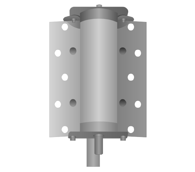
Andrew multiband high / low power splitter

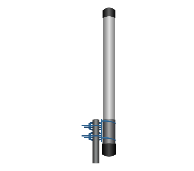
Andrew multi-band indoor omnidirectional antenna

Panel sector directional antenna
Omni directional antenna
Yagi directional antenna
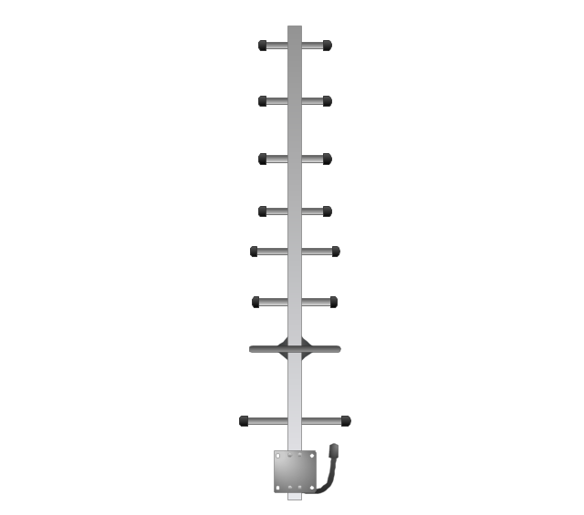
Yagi integrated downconverter

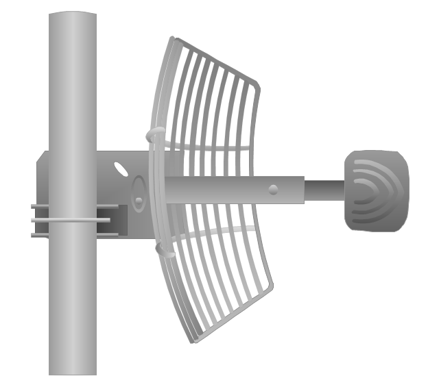
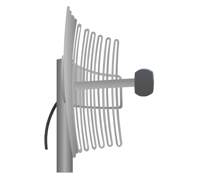
Grid antenna
Loop antenna
FireTide HotPort® 6000 wireless mesh nodes
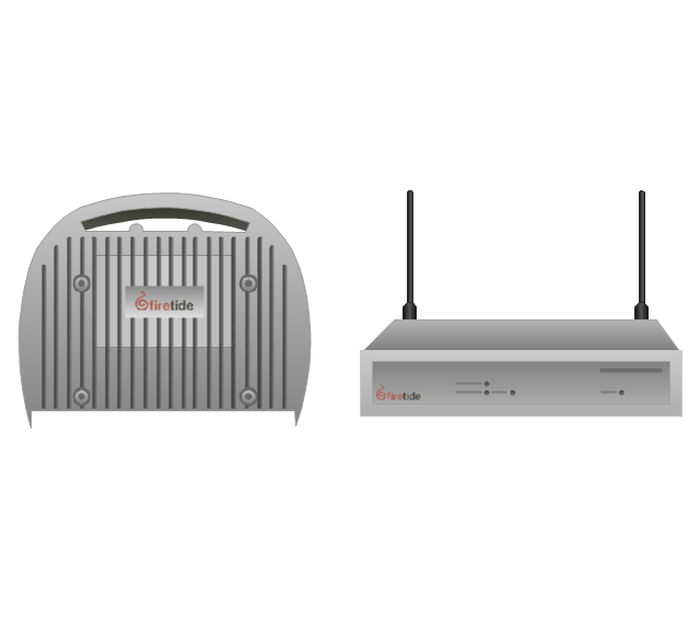
FireTide HotPoint® wireless access point
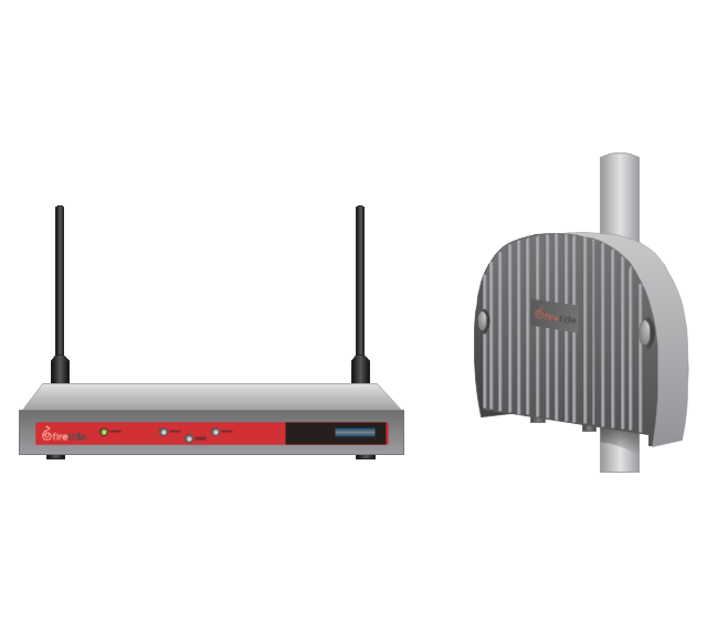
FireTide HotClient Customer Premises Equipment (CPE)
-telecom-equipment---vector-stencils-library.png--diagram-flowchart-example.png)
- Physical And Logical Network Layout
- Explain With The Help Of Diagram Satellite Network Components
- How The Components Of A Computer Communicate Diagram
- Process Flowchart | Local area network (LAN). Computer and ...
- Diagram Physical Topologies | Network Topologies | Logical ...
- Home area networks (HAN). Computer and Network Examples ...
- What Are Conponents Of Computer Based Information System
- Components Of Environment Draw The Diagram
- Sketch Of A Lan
- Wide area network (WAN) topology. Computer and Network Examples
- Network Layout Floor Plans | Home area networks (HAN). Computer ...
- Network Architecture | Local area network (LAN). Computer and ...
- Network Diagram Software Home Area Network | Near field ...
- Switch Diagram In Computer Communication
- Network Structure Software Download
- Local area network (LAN). Computer and Network Examples ...
- Computer Network Architecture. Computer and Network Examples ...
- Design Element: Computer and Network for Network Diagrams ...
- Lan Architecter Digram
- The Diagram Of Lan And Wan