Electrical Symbols — Integrated Circuit

Electrical Symbols — Rotating Equipment

Electrical Symbols — Analog and Digital Logic

The vector stencils library "Power sources" contains 9 element symbols of power sources and batteries for drawing the electrical schematics and electronic circuit diagrams.
"A power supply is a device that supplies electric power to an electrical load. The term is most commonly applied to electric power converters that convert one form of electrical energy to another, though it may also refer to devices that convert another form of energy (mechanical, chemical, solar) to electrical energy. A regulated power supply is one that controls the output voltage or current to a specific value; the controlled value is held nearly constant despite variations in either load current or the voltage supplied by the power supply's energy source.
Every power supply must obtain the energy it supplies to its load, as well as any energy it consumes while performing that task, from an energy source. Depending on its design, a power supply may obtain energy from:
(1) Electrical energy transmission systems. Common examples of this include power supplies that convert AC line voltage to DC voltage.
(2) Energy storage devices such as batteries and fuel cells.
(3) Electromechanical systems such as generators and alternators.
(4) Solar power." [Power supply. Wikipedia]
The shapes example "Design elements - Power sources" was drawn using the ConceptDraw PRO diagramming and vector drawing software extended with the Electrical Engineering solution from the Engineering area of ConceptDraw Solution Park.
Power source symbols

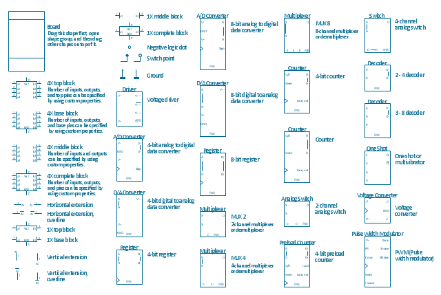
The vector stencils library "Integrated circuit" contains 43 component symbols: transducers, rotary devices, converters, registers, analog switches, counters, registers, decoders, and multiplex transmitters.
"An integrated circuit or monolithic integrated circuit (also referred to as an IC, a chip, or a microchip) is a set of electronic circuits on one small plate ("chip") of semiconductor material, normally silicon. This can be made much smaller than a discrete circuit made from independent components.
Integrated circuits are used in virtually all electronic equipment today and have revolutionized the world of electronics. Computers, mobile phones, and other digital home appliances are now inextricable parts of the structure of modern societies, made possible by the low cost of producing integrated circuits." [Integrated circuit. Wikipedia]
The symbols example "Design elements - Integrated circuit" was drawn using the ConceptDraw PRO diagramming and vector drawing software extended with the Electrical Engineering solution from the Engineering area of ConceptDraw Solution Park.
Integrated circuit components
Electrical Symbols, Electrical Diagram Symbols

Electrical Symbols — Composite Assemblies

Network Diagram Software. LAN Network Diagrams. Physical Office Network Diagrams


Wiring Diagrams with ConceptDraw DIAGRAM

The vector stencils library "Analog and digital logic" contains 40 element symbols of logic (threshold) gates, bistable current switches, current controllers, regulators, electrical generators, and amplifiers.
Use it for drawing the digital and analog functions in electronic circuit diagrams and electrical schematics.
"Analogue electronics (or analog in American English) are electronic systems with a continuously variable signal, in contrast to digital electronics where signals usually take only two different levels. The term "analogue" describes the proportional relationship between a signal and a voltage or current that represents the signal." [Analogue electronics. Wikipedia]
"Digital electronics, or digital (electronic) circuits, represent signals by discrete bands of analog levels, rather than by a continuous range. All levels within a band represent the same signal state. Relatively small changes to the analog signal levels due to manufacturing tolerance, signal attenuation or parasitic noise do not leave the discrete envelope, and as a result are ignored by signal state sensing circuitry.
In most cases the number of these states is two, and they are represented by two voltage bands: one near a reference value (typically termed as "ground" or zero volts) and a value near the supply voltage, corresponding to the "false" ("0") and "true" ("1") values of the Boolean domain respectively.
Digital techniques are useful because it is easier to get an electronic device to switch into one of a number of known states than to accurately reproduce a continuous range of values.
Digital electronic circuits are usually made from large assemblies of logic gates, simple electronic representations of Boolean logic functions." [Digital electronics. Wikipedia]
The example "Design elements - Analog and digital logic" was drawn using the ConceptDraw PRO diagramming and vector drawing software extended with the Electrical Engineering solution from the Engineering area of ConceptDraw Solution Park.
Analog and digital logic elements

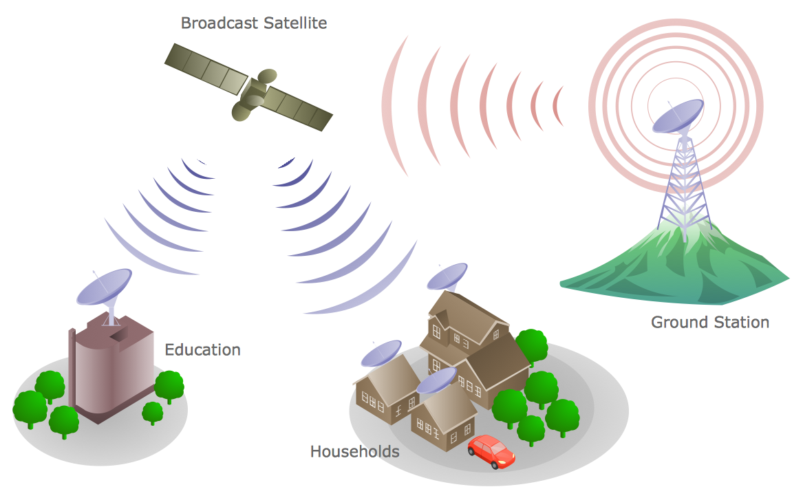
Telecommunications Network
- Voltage Converter Symbols
- Voltag Converter Electrical Symbol
- Electrical Symbols — Power Sources | Design elements - Power ...
- Electrical Symbols — Power Sources | Electrical Symbols — Thermo ...
- Electrical Symbols — Transformers and Windings | Electrical ...
- Electrical Symbols — Power Sources | Functional Block Diagram ...
- Electrical Symbols — Power Sources | Electrical Symbols , Electrical ...
- Electrical Symbols — Stations | Electrical Symbols — Transformers ...
- Electrical Symbols — Power Sources | Electrical Symbols — Thermo ...
- Electrical Symbols — Power Sources | Electrical Symbols , Electrical ...
- How To use Electrical and Telecom Plan Software | How To use ...
- Electrical Symbols , Electrical Diagram Symbols | Circuits and Logic ...
- Electrical Diagram Software | Bipolar current mirror - Circuit diagram ...
- Electrical Symbols — Integrated Circuit | Design elements ...
- Visio Files and ConceptDraw | Integrated circuit - Vector stencils ...
- Electrical Symbols — Thermo | Electrical Symbols — Analog and ...
- Electrical Diagram | Electrical Engineering | Electrical Symbols ...
- Electrical Engineering | Bipolar current mirror - Circuit diagram ...
- Electrical Symbols — Terminals and Connectors | Electrical Drawing ...