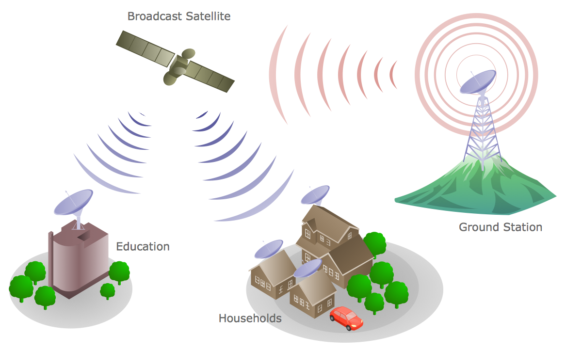
Example 1. Telecommunications Network - Communication Medium Diagram
Telecommunication Network Diagrams Solution contains large number of libraries with variety of predesigned vector shapes which allow you design any type of telecommunications network in minutes.
All what you need is drag the needed objects from the libraries, arrange them in desired order, add the text, type the title, create colorful background, and your own beautiful and attractive diagram will be ready. It's very simple!

Example 2. Telecommunication Network Diagrams Solution in ConceptDraw STORE
You can also use the ready samples and templates prepared by professionals in ConceptDraw DIAGRAM and offered in ConceptDraw STORE.

Example 3. Telecommunications Network - BreezeMAX
The samples you see on this page were created in ConceptDraw DIAGRAM using the Telecommunication Network Diagrams Solution for ConceptDraw DIAGRAM Solution Park. Every telecommunications network presented on this page or in ConceptDraw STORE successfully demonstrate solution's capabilities and professional results you can achieve. An experienced user spent 10 minutes creating every of these samples.
Use the Telecommunication Network Diagrams Solution for ConceptDraw DIAGRAM software to create your own professional looking Telecommunications Network of any complexity fast and easy.
All source documents are vector graphic documents. They are available for reviewing, modifying, or converting to a variety of formats (PDF file, MS PowerPoint, MS Visio, and many other graphic formats) from the ConceptDraw STORE. The Telecommunication Network Diagrams Solution is available for all ConceptDraw DIAGRAM or later users.
TEN RELATED HOW TO's:
Using the predesigned objects, templates and samples of the Computer and Networks Solution for ConceptDraw DIAGRAM you can create your own professional Computer Network Diagrams quick and easy.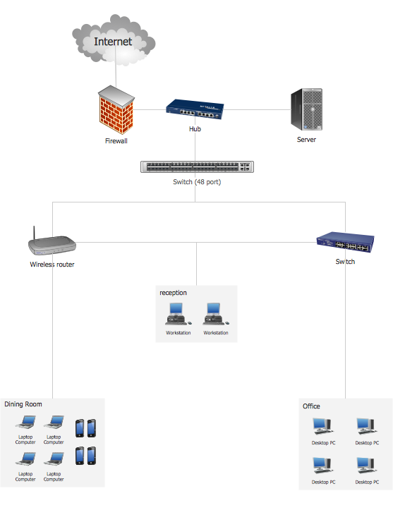
Picture: Hotel Network Topology
Related Solution:
A list of parameters on which networks differ is very long. A large network with a range up to 50 kilometers is called metropolitan area network (MAN), and this type of network can include several local area networks. Metropolitan networks in their turn connect into global area networks.
Here you will see a Metropolitan Area Network (MAN). This is an extensive network which occupies a large territory including a few buildings or even the whole city. The space of the MAN is bigger than LAN, but lower than WAN. MAN comprise a lot of communication equipment and delivers the Internet connection to the LANs in the city area. Computer and Networks solution for ConceptDraw DIAGRAM provides a set of libraries with ready-to-use vector objects to design various kinds of computer networks.
Picture: Metropolitan area networks (MAN). Computer and Network Examples
Related Solution:
The ConceptDraw vector stencils library Cisco Multimedia, Voice, Phone contains equipment symbols for drawing the computer network diagrams.
Picture: Cisco Multimedia, Voice, Phone. Cisco icons, shapes, stencils and symbols
Related Solution:
Electrical plan is a document that is developed during the first stage of the building design. This scheme is composed of conventional images or symbols of components that operate by means of electric energy. To simplify the creation of these schemes you can use house electrical plan software, which will not require a long additional training to understand how to use it. You only need to install the necessary software ant it’s libraries and you’ll have one less problem during the building projection.
Any building contains a number of electrical systems, including switches, fixtures, outlets and other lightening equipment. All these should be depicted in a building electrical plans and included to general building documentation. This home electrical plan displays electrical and telecommunication devices placed to a home floor plan. On the plan, each electrical device is referenced with the proper symbol. Electrical symbols are used for universal recognition of the building plan by different persons who will be working on the construction. Not all possible electric symbols used on a certain plan, so the symbols used in the current home plan are included to a legend. The electrical home plan may be added as a separate document to a complete set of building plans.
Picture: How To use House Electrical Plan Software
Related Solution:
ConceptDraw DIAGRAM software supplied with Telecom and AV Circuits solution offers wide abilities for designing thematic diagrams, infographics and illustrations. You can easily create illustrative reviews of TV antennas, show the different types of TV antennas from the basic indoor antennas to amplified outdoor antennas, identify their advantages and gaps. You can offer the testing results to help detect the best TV antenna from the variety available on the market. It is also a way to illustrate the connection of antennas, how to position them to get the best reception, which channels are available and how to set up your equipment.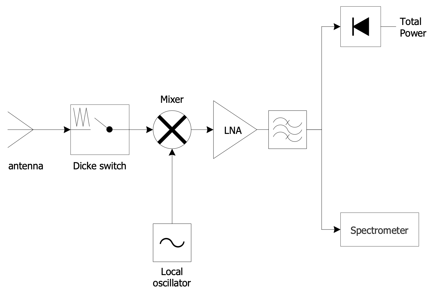
Picture: Antenna TV
Enterprise systems engineers almost every day face the necessity of network diagrams. We should also take into account that Cisco network design is not only limited to computer networks, but, furthermore, you can design telephone networks and much more. You can build an hierarchical model of your network to get better performance and reliability.
This network diagram represents the utilization of Conceptdraw DIAGRAM for network documentation creation. The diagram shows schematically the structure of a node of a large Internet service provider, which is completed on the basis of Cisco equipment. This diagram was designed using the vector library containing the images of Cisco equipment, supplied with Cisco Network Diagrams solution. In total, the solution has more than ten libraries including more than 500 vector icons of Cisco equipment.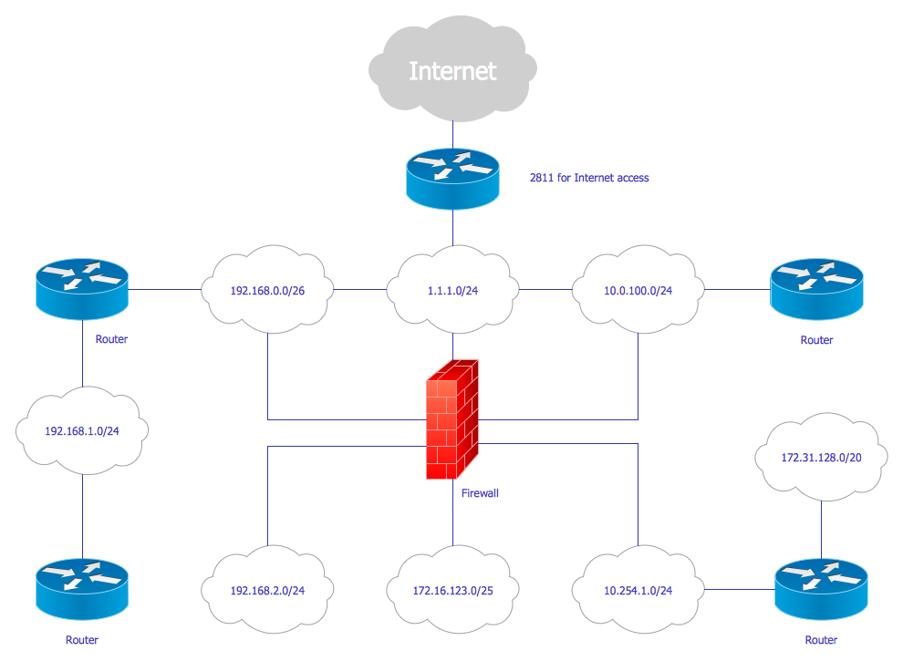
Picture: Cisco Network Design
Related Solution:
ConceptDraw DIAGRAM Comparison with Omnigraffle Professional and MS Visio. All source ConceptDraw documents are vector graphic documents. They are available for reviewing, modifying, or converting to a variety of formats: PDF file, MS PowerPoint, MS Visio, and many other graphics formats.
Picture: ConceptDraw DIAGRAM Comparison with Omnigraffle Professional and MS Visio
Related Solution:
Astronomy solution provides the Stars and Planets library with wide variety of solar system symbols. You can find here vector objects of solar system, of stars and planets of the universe.
To quickly draw any astronomy illustration: create new document and simply drag the needed solar system symbols from the Stars and Planets library, arrange them and add the text. You can also use the predesigned templates and samples from the ConceptDraw STORE as the base for your own sun solar system illustrations, astronomy and astrology drawings.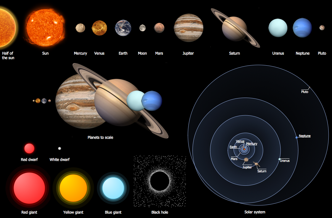
Picture: Solar System Symbols
Related Solution:
ConceptDraw DIAGRAM diagramming and vector drawing software extended with Rack Diagrams solution from the Computer and Networks area is a powerful rack diagrams and server rack diagrams drawing software.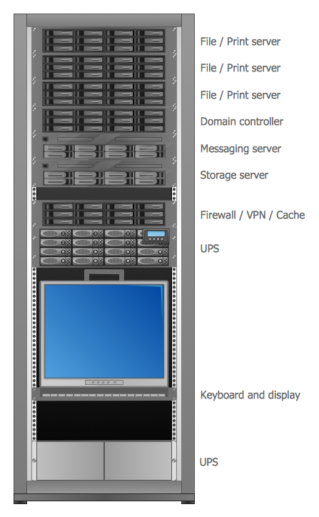
Picture: Server
Related Solution:
How to draw Telecommunications Network Diagram quick, easy and effective? ConceptDraw DIAGRAM offers the unique Telecommunication Network Diagrams Solution from the Computer and Networks Area which will help you.Picture: Telecommunications Network
Related Solution:


