Electrical Symbols — IGFET

Electrical Symbols — Switches and Relays

Electrical Symbols — MOSFET

Electrical Symbols — Transistors

Electrical Symbols — Semiconductor

Mechanical Drawing Symbols

Process Flowchart


Electrical Symbols — Semiconductor Diodes

Local area network (LAN). Computer and Network Examples
. Computer and Network Examples")

Network Diagram Software LAN Network Diagrams & Diagrams for LAN Physical Office Network Diagrams

The vector stencils library "Logic gate diagram" contains 17 element symbols for drawing the logic gate diagrams.
"To build a functionally complete logic system, relays, valves (vacuum tubes), or transistors can be used. The simplest family of logic gates using bipolar transistors is called resistor-transistor logic (RTL). Unlike simple diode logic gates (which do not have a gain element), RTL gates can be cascaded indefinitely to produce more complex logic functions. RTL gates were used in early integrated circuits. For higher speed and better density, the resistors used in RTL were replaced by diodes resulting in diode-transistor logic (DTL). Transistor-transistor logic (TTL) then supplanted DTL. As integrated circuits became more complex, bipolar transistors were replaced with smaller field-effect transistors (MOSFETs); see PMOS and NMOS. To reduce power consumption still further, most contemporary chip implementations of digital systems now use CMOS logic. CMOS uses complementary (both n-channel and p-channel) MOSFET devices to achieve a high speed with low power dissipation." [Logic gate. Wikipedia]
The symbols example "Design elements - Logic gate diagram" was drawn using the ConceptDraw PRO diagramming and vector drawing software extended with the Electrical Engineering solution from the Engineering area of ConceptDraw Solution Park.
Logic gate symbols

Daisy Chain Network Topology

How To use Switches in Network Diagram

3 Circle Venn Diagram. Venn Diagram Example

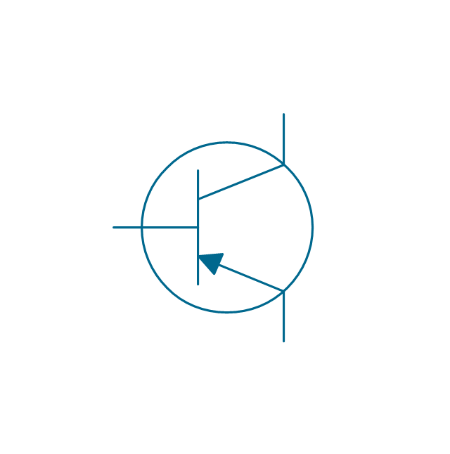
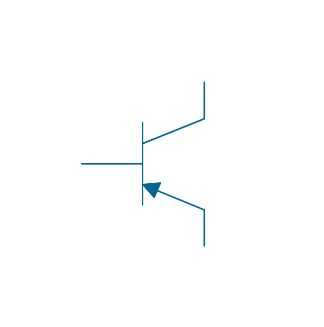
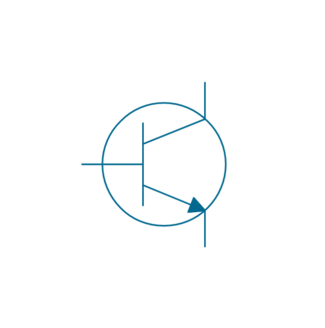
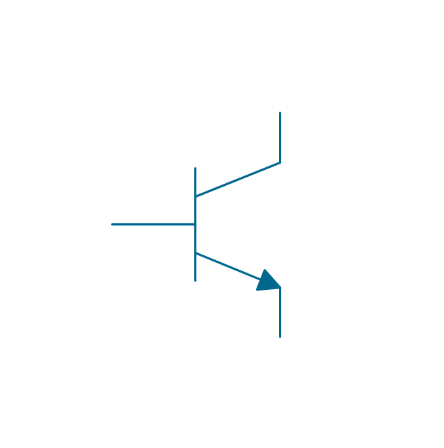
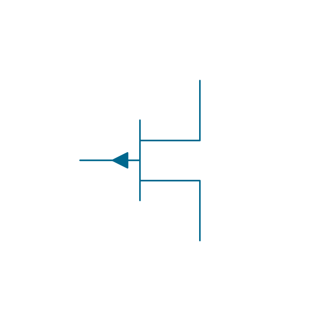
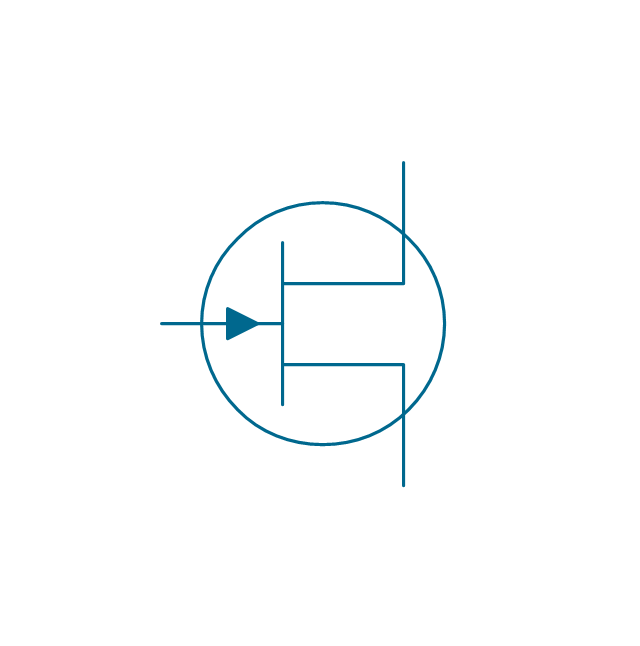
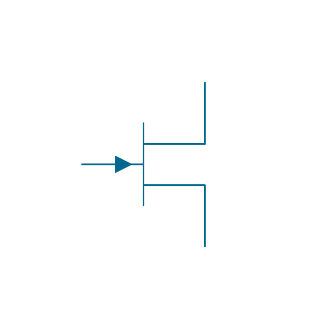
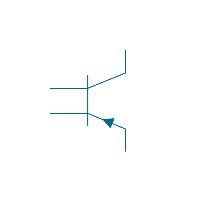
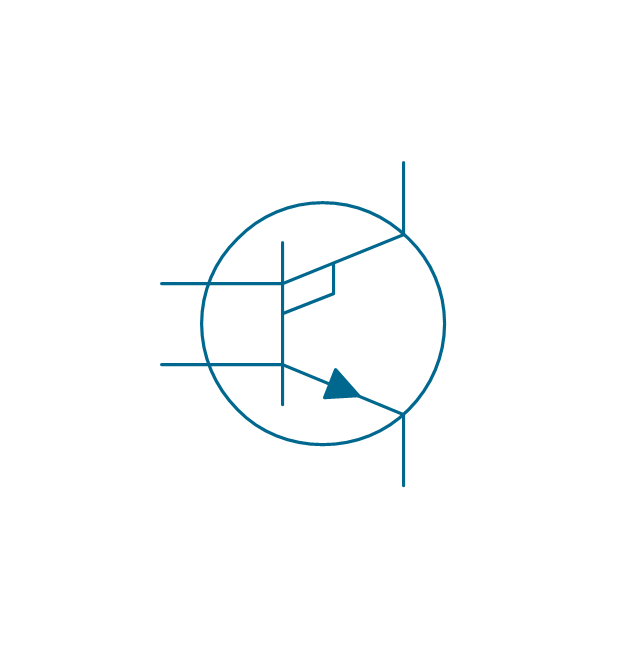
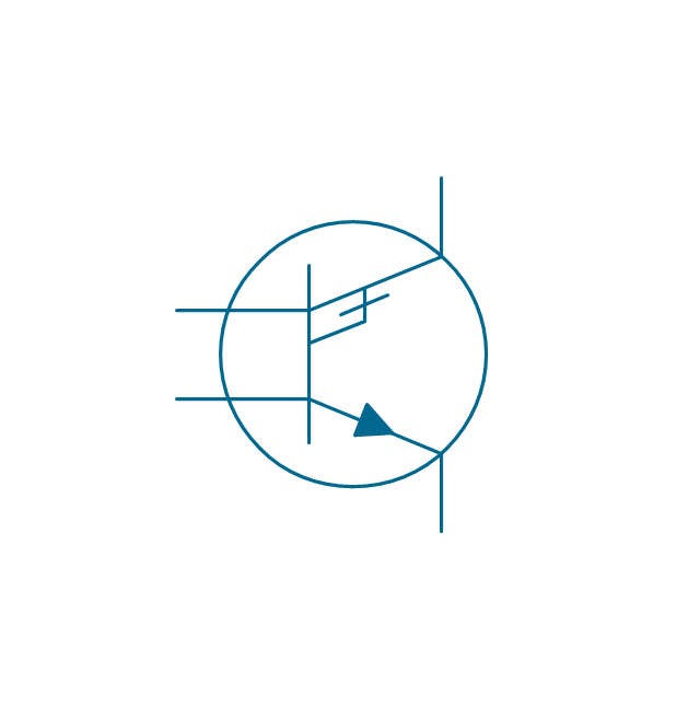
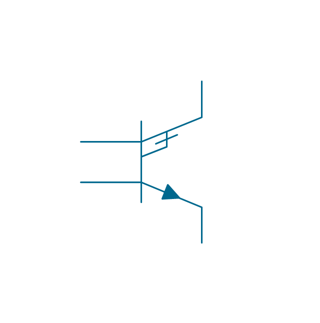
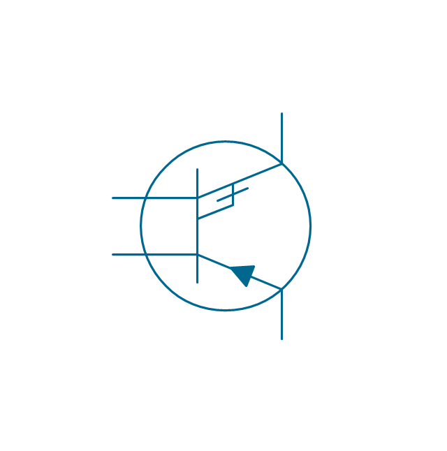
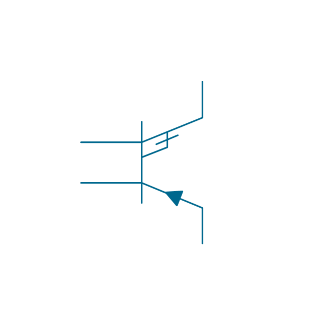
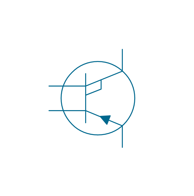
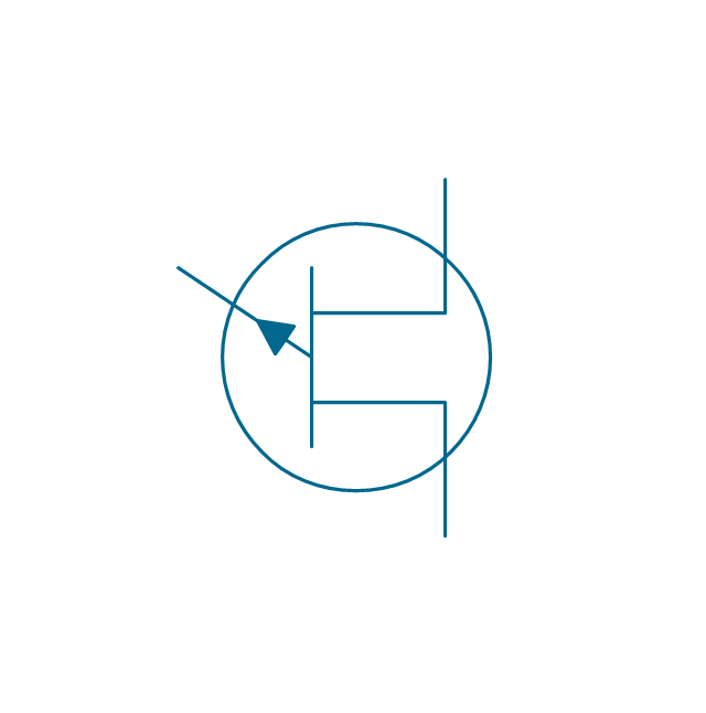
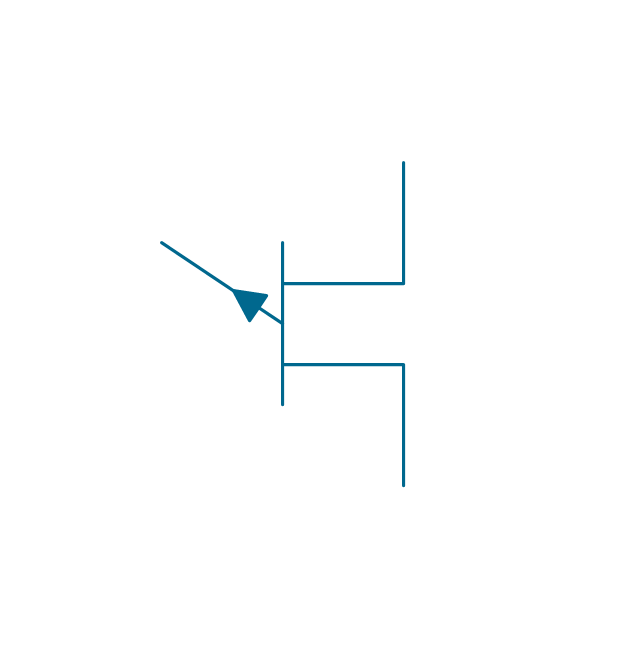
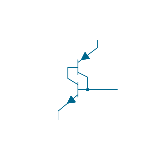
The vector stencils library "Transistors" contains 30 symbols of transistors.
Use these shapes for drawing electronic schematics and circuit diagrams in the ConceptDraw PRO diagramming and vector drawing software extended with the Electrical Engineering solution from the Engineering area of ConceptDraw Solution Park.
www.conceptdraw.com/ solution-park/ engineering-electrical
Use these shapes for drawing electronic schematics and circuit diagrams in the ConceptDraw PRO diagramming and vector drawing software extended with the Electrical Engineering solution from the Engineering area of ConceptDraw Solution Park.
www.conceptdraw.com/ solution-park/ engineering-electrical
BJT, PNP, env
BJT, PNP
BJT, NPN, env
BJT, NPN
JFET, P, env

JFET, P
JFET, N, env
JFET, N
Transverse biased base, PNP, env

Transverse biased base, PNP
Transverse biased base, NPN, env

Transverse biased base, NPN

Ohmic, NPIN, env
Ohmic, NPIN

Ohmic, NPIP, env
Ohmic, NPIP
Ohmic, PNIN, env
Ohmic, PNIN
Ohmic, PNIP, env
Ohmic, PNIP

Unijunction FET, P, env
Unijunction FET, P
Unijunction FET, N, env

Unijunction FET, N

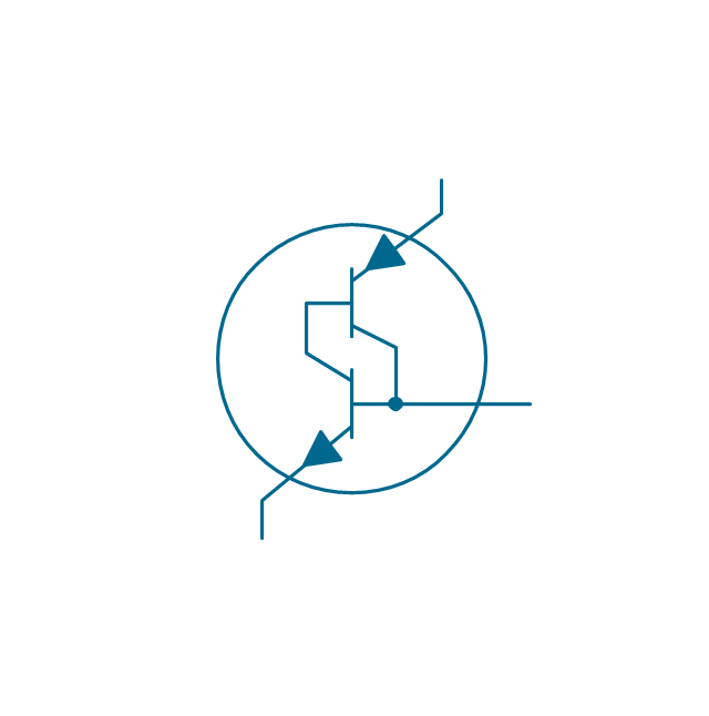
Darlington transistor, PNP, env
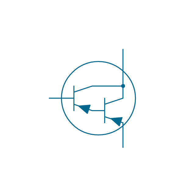
Darlington transistor, PNP
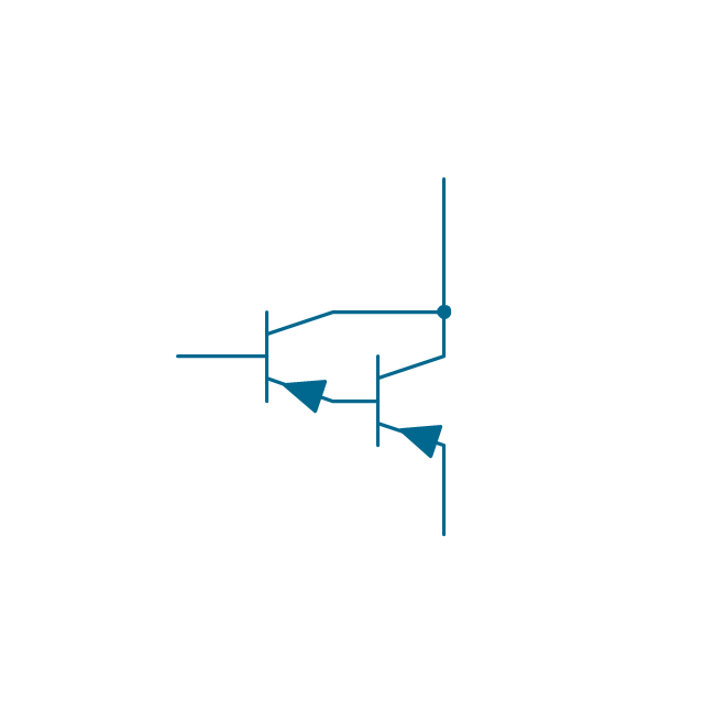
Darlington transistor, NPN, env
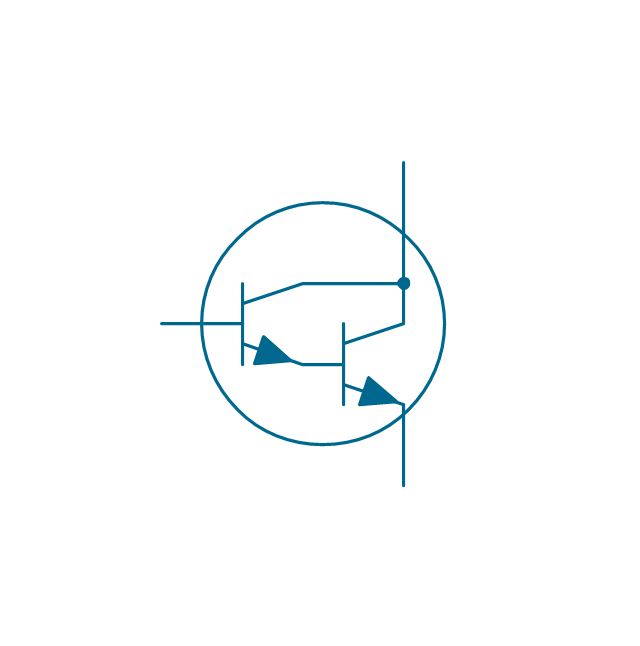
Darlington transistor, NPN

Transistor latch, env
Transistor latch
- Electrical Drawing Software and Electrical Symbols | Electrical ...
- Different Electrical Symbols In An Electric Circuit And Their Uses
- Design elements - Transistors | Electrical Symbols — MOSFET ...
- Mosfet Symbol
- Electrical Drawing Software and Electrical Symbols | Amplifier ...
- Electrical Symbols , Electrical Diagram Symbols | How To use House ...
- Types Of Diode And Their Symbols
- Electrical Symbols — Transistors | Design elements - Transistors ...
- How To use House Electrical Plan Software | Switches and relays ...
- Electrical Symbols — Logic Gate Diagram | Electrical Symbols ...
- Schematic Circuit Symbols
- Symbols That Service Engineers Use In A Circuit Digram
- Circuits and Logic Diagram Software | Electrical Drawing Software ...
- Electrical Symbols — Logic Gate Diagram | Circuits and Logic ...
- Design elements - Logic gate diagram | Electrical Symbols ...
- Electrical Symbols — Semiconductor | Electrical Symbols , Electrical ...
- How To use House Electrical Plan Software | Value Stream Mapping ...
- How To use House Electrical Plan Software | Electrical Symbols ...
- Circuits and Logic Diagram Software | Design elements ...
- Home Electrical Plan | Electrical Symbols , Electrical Diagram ...