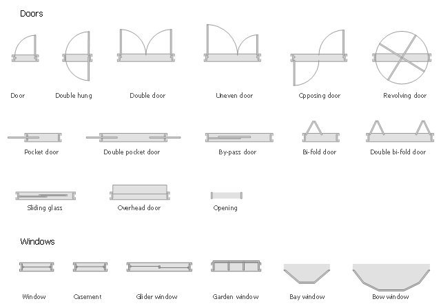
The design elements library Doors contains 69 symbols of doors.
The design elements library Windows contains 34 symbols of windows and casements.
"A door is an opening or closing structure used to block off an entrance, typically consisting of an interior side that faces the inside of a space and an exterior side that faces the outside of that space. While in some cases the interior side of a door may match its exterior side, in other cases there are sharp contrasts between the two sides, such as in the case of the vehicle door. In addition, doors typically consist of a panel that swings on hinges or that slides or spins inside of a space." [Door. Wikipedia]
"A window is an opening in a wall, door or vehicle that allows the passage of light and, if not closed or sealed, air and sound. Modern windows are usually glazed or covered in some other transparent or translucent material. Windows are held in place by frames. Many glazed windows may be opened, to allow ventilation, or closed, to exclude inclement weather." [Window. Wikipedia]
Use the shapes libraries Doors and Windows to create house plans, home plans, floor plan layouts and home designs using the ConceptDraw PRO diagramming and vector drawing software.
The vector stencils libraries Doors and Windows are provided by the Floor Plans solution from the Building Plans area of ConceptDraw Solution Park.
Basic Flowchart Symbols and Meaning


The design elements library Doors contains 69 symbols of doors.
The design elements library Windows contains 34 symbols of windows and casements.
"A door is an opening or closing structure used to block off an entrance, typically consisting of an interior side that faces the inside of a space and an exterior side that faces the outside of that space. While in some cases the interior side of a door may match its exterior side, in other cases there are sharp contrasts between the two sides, such as in the case of the vehicle door. In addition, doors typically consist of a panel that swings on hinges or that slides or spins inside of a space." [Door. Wikipedia]
"A window is an opening in a wall, door or vehicle that allows the passage of light and, if not closed or sealed, air and sound. Modern windows are usually glazed or covered in some other transparent or translucent material. Windows are held in place by frames. Many glazed windows may be opened, to allow ventilation, or closed, to exclude inclement weather." [Window. Wikipedia]
Use the shapes libraries Doors and Windows to create house plans, home plans, floor plan layouts and home designs using the ConceptDraw PRO diagramming and vector drawing software.
The vector stencils libraries Doors and Windows are provided by the Floor Plans solution from the Building Plans area of ConceptDraw Solution Park.
The design elements library Windows contains 34 symbols of windows and casements.
"A door is an opening or closing structure used to block off an entrance, typically consisting of an interior side that faces the inside of a space and an exterior side that faces the outside of that space. While in some cases the interior side of a door may match its exterior side, in other cases there are sharp contrasts between the two sides, such as in the case of the vehicle door. In addition, doors typically consist of a panel that swings on hinges or that slides or spins inside of a space." [Door. Wikipedia]
"A window is an opening in a wall, door or vehicle that allows the passage of light and, if not closed or sealed, air and sound. Modern windows are usually glazed or covered in some other transparent or translucent material. Windows are held in place by frames. Many glazed windows may be opened, to allow ventilation, or closed, to exclude inclement weather." [Window. Wikipedia]
Use the shapes libraries Doors and Windows to create house plans, home plans, floor plan layouts and home designs using the ConceptDraw PRO diagramming and vector drawing software.
The vector stencils libraries Doors and Windows are provided by the Floor Plans solution from the Building Plans area of ConceptDraw Solution Park.
The design elements library Walls, shell and structure contains 29 symbols of structural elements: walls, rooms, windows, doors, pillars.
Use the vector stencils library Walls, shell and structure to draw the floor plans and other architectural drawings, blueprints, home and building interior design, space layout plans, construction and house framing diagrams using the ConceptDraw PRO diagramming and vector drawing software.
"A wall is a horizontal structure, usually solid, that defines and sometimes protects an area. Most commonly, a wall delineates a building and supports its superstructure, separates space in buildings into sections, or protects or delineates a space in the open air. There are three principal types of structural walls: building walls, exterior boundary walls, and retaining walls.
Building walls have one main purpose: to support roofs and ceilings. Such walls most often have three or more separate components. In today's construction, a building wall will usually have the structural elements (such as 2×4 studs in a house wall), insulation, and finish elements or surface (such as drywall or panelling). In addition, the wall may house various types of electrical wiring or plumbing. Electrical outlets are usually mounted in walls.
Building walls frequently become works of art externally and internally, such as when featuring mosaic work or when murals are painted on them; or as design foci when they exhibit textures or painted finishes for effect.
In architecture and civil engineering, the term curtain wall refers to the facade of a building which is not load-bearing but functions as decoration, finish, front, face, or history preservation." [Wall. Wikipedia]
This shapes library Walls, shell and structure is provided by the Floor Plans solution from the Building Plans area of ConceptDraw Solution Park.

Network Diagram Software LAN Network Diagrams & Diagrams for LAN Physical Office Network Diagrams


The vector stencils library "Microsoft Exchange" contains 17 symbols of Microsoft Exchange elements for drawing the logical structure diagrams of Active Directory trees.
"Windows Messaging, initially called Microsoft Exchange, is an e-mail client that was included with Windows 95 (beginning with OSR2), 98 and Windows NT 4.0. ...
Microsoft Exchange gained wide usage with the release of Windows 95, as this was the only mail client that came bundled with it. In 1996, it was renamed to Windows Messaging, because of the upcoming release of Microsoft Exchange Server, and continued to be included throughout later releases of Windows up until the initial release of Windows 98, which by then included Outlook Express 4.0 as the default mail client.
The Windows Messaging email client had two branches of successors:
(1) In software bundled with Windows itself, these were Internet Mail and News in Windows 95 (and bundled with Internet Explorer 3), which was succeeded by Outlook Express 4.0 in Windows 98 (bundled with Internet Explorer 4.0 in Windows 95) and throughout newer Windows systems. These did not use the .pst file type.
(2) Microsoft Outlook became the professional-grade and more direct successor of MS Exchange Client, which still uses the .pst file type." [Windows Messaging. Wikipedia]
The symbols example "Microsoft Exchange - Vector stencils library" was created using the ConceptDraw PRO diagramming and vector drawing software extended with the Active Directory Diagrams solution from the Computer and Networks area of ConceptDraw Solution Park.
www.conceptdraw.com/ solution-park/ active-directory-diagrams
Exchange organization

Storage group
Sessions
Message formats

Exchange servers

Exchange server
Public folders
Recipient update service
Recipient policy
Message delivery
Mailbox
Exchange virtual server

HTTP virtual directory

Public store
Mailbox store
IMAP virtual server
NNTP virtual server
ERD Symbols and Meanings


Windows Azure

The vector stencils library "Network layout floorplan" contain 34 symbol icons for drawing computer network floor plans and communication equipment and cabling layouts.
"Networking hardware may also be known as network equipment or computer networking devices. Units which are the last receiver or generate data are called hosts or data terminal equipment.
All these terms refer to devices facilitating the use of a computer network. Specifically, they mediate data in a computer network. ...
Typically, networking hardware includes gateways, routers, network bridges, switches, hubs, and repeaters. But it also includes hybrid network devices such as multilayer switches, protocol converters, bridge routers, proxy servers, firewalls, network address translators, multiplexers, network interface controllers, wireless network interface controllers, modems, ISDN terminal adapters, line drivers, wireless access points, networking cables and other related hardware.
The most common kind of networking hardware today is a copper-based Ethernet adapter because of its standard inclusion on most modern computer systems. Wireless networking has, however, become increasingly popular, especially for portable and handheld devices.
Other hardware prevalent in computer networking includes data center equipment (such as file servers, database servers and storage areas), network services (such as DNS, DHCP, email, etc.) as well as devices which assure content delivery." [Networking hardware. Wikipedia]
The shapes example "Design elements - Network layout floorplan" was created using the ConceptDraw PRO diagramming and vector drawing software extended with the Network Layout Floor Plans solution from the Computer and Networks area of ConceptDraw Solution Park.
Network layout floor plan symbols

The vector stencils library Alarm and access control contains 80 symbols of digital proximity equipment, locking hardware, and access control equipment.
"An alarm device or system of alarm devices gives an audible, visual or other form of alarm signal about a problem or condition. Alarm devices are often outfitted with a siren." [Alarm device. Wikipedia]
"An access control point, which can be a door, turnstile, parking gate, elevator, or other physical barrier, where granting access can be electronically controlled. Typically, the access point is a door. An electronic access control door can contain several elements. At its most basic, there is a stand-alone electric lock. The lock is unlocked by an operator with a switch. To automate this, operator intervention is replaced by a reader. The reader could be a keypad where a code is entered, it could be a card reader, or it could be a biometric reader. Readers do not usually make an access decision, but send a card number to an access control panel that verifies the number against an access list. To monitor the door position a magnetic door switch can be used. In concept, the door switch is not unlike those on refrigerators or car doors. Generally only entry is controlled, and exit is uncontrolled. In cases where exit is also controlled, a second reader is used on the opposite side of the door. In cases where exit is not controlled, free exit, a device called a request-to-exit (REX) is used. Request-to-exit devices can be a push-button or a motion detector. When the button is pushed, or the motion detector detects motion at the door, the door alarm is temporarily ignored while the door is opened. Exiting a door without having to electrically unlock the door is called mechanical free egress. This is an important safety feature. In cases where the lock must be electrically unlocked on exit, the request-to-exit device also unlocks the door." [Access control. Wikipedia]
Use the design elements library Alarm and access control for drawing layout floor plans, blueprints, and wiring diagrams of intrusion systems, time and attendance systems, card and code access control security systems, internal and external security control systems using the ConceptDraw PRO diagramming and vector drawing software.
The shapes library Alarm and access control is included in the Security and Access Plans solution from the Building Plans area of ConceptDraw Solution Park.
Alarm and access control symbols

How To use House Electrical Plan Software


Symbol for Pool Table for Floor Plans

Flowchart Software

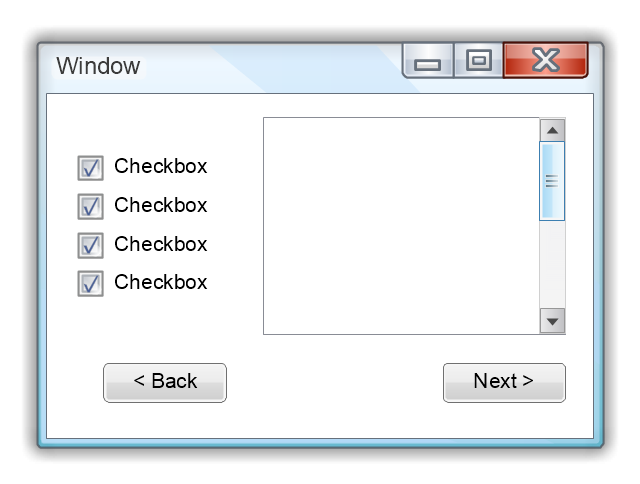
Use this template to prototype and design the Windows graphic user interface.
"In human–computer interaction, WIMP stands for "windows, icons, menus, pointer", denoting a style of interaction using these elements of the user interface. ... Other expansions are sometimes used, substituting "mouse" and "mice" or "pull-down menu" and "pointing", for menus and pointer, respectively. ...
In a WIMP system:
(1) A window runs a self-contained program, isolated from other programs that (if in a multi-program operating system) run at the same time in other windows.
(2) An icon acts as a shortcut to an action the computer performs (e.g., execute a program or task).
(3) A menu is a text or icon-based selection system that selects and executes programs or tasks.
(4) The pointer is an onscreen symbol that represents movement of a physical device that the user controls to select icons, data elements, etc.
(5) cut, copy, and paste.
This style of system improves human–computer interaction (HCI) by emulating real-world interactions and providing better ease of use for non-technical people - both novice and power users. Users can carry skill at a standardized interface from one application to another.
Due to the nature of the WIMP system, simple commands can be chained together to undertake a group of commands that would have taken several lines of command line instructions." [WIMP (computing). Wikipedia]
The Windows Vista graphic user interface template for the ConceptDraw PRO diagramming and vector drawing software is included in the Graphic User Interface solution from the Software Development area of ConceptDraw Solution Park.
Windows GUI template
Physics Symbols

- The Symbol For Doors And Windows In Floor Plan
- Symbol Of Window
- Window And Door Symbols
- Design elements - Doors and windows | Symbol for Pool Table for ...
- Window Symbol
- Design elements - Doors and windows | How To use Appliances ...
- Window Symbol Floor Plan
- Doors And Window Symbol
- Symbol for Pool Table for Floor Plans | Design elements - Doors and ...
- Sliding Glass Door Symbol
- Symbol Of Door And Window On Plan
- Window Symbols On A Floor Plan
- Design elements - Doors and windows | Design elements - Alarm ...
- The Symbol Which Is Use For Door And Window In Civil Articatural
- Window Symbol In Floor Plan
- Window And Ventilator Symbol On Plan
- Symbol Window For Glass Windows
- Symbol Of Door And Windows In Drawing Of Building
- Design elements - Doors and windows
- House Plan Door Windows Symbols