How To use House Electrical Plan Software


The vector stenvils library "Outlets" contains 57 symbols of electrical outlets for drawing building interior design, electrical floor plans and layouts of AC power plugs and sockets.
"AC power plugs and sockets are devices that allow electrically operated equipment to be connected to the primary alternating current (AC) power supply in a building. Electrical plugs and sockets differ in voltage and current rating, shape, size and type of connectors. The types used in each country are set by national standards, some of which are listed in the IEC technical report TR 60083, Plugs and socket-outlets for domestic and similar general use standardized in member countries of IEC.
Plugs and sockets for portable appliances started becoming available in the 1880s, to replace connections to light sockets with easier to use wall-mounted outlets. A proliferation of types developed to address the issues of convenience and protection from electric shock. Today there are approximately 20 types in common use around the world, and many obsolete socket types are still found in older buildings. Co-ordination of technical standards has allowed some types of plugs to be used over wide regions to facilitate trade in electrical appliances, and for the convenience of travellers and consumers of imported electrical goods. Some multi-standard sockets allow use of several different types of plugs; improvised or unapproved adapters between incompatible sockets and plugs may not provide the full safety and performance of an approved adapter." [AC power plugs and sockets. Wikipedia]
The example "Design elements - Outlets" was created using the ConceptDraw PRO diagramming and vector drawing software extended with the Electric and Telecom Plans solution from the Building plans area of ConceptDraw Solution Park.
Electrical outlet symbols

The vector stencils library "UML component diagrams" contains 36 symbols for the ConceptDraw PRO diagramming and vector drawing software.
"In the Unified Modeling Language, a component diagram depicts how components are wired together to form larger components and or software systems. They are used to illustrate the structure of arbitrarily complex systems. ...
Symbols.
This may have a visual stereotype in the top right of the rectangle of a small rectangle with two even smaller rectangles jutting out on the left.
The lollipop, a small circle on a stick represents an implemented or provided interface. The socket symbol is a semicircle on a stick that can fit around the lollipop. This socket is a dependency or needed interface." [Component diagram. Wikipedia]
The example "Design elements - UML component diagrams" is included in the Rapid UML solution from the Software Development area of ConceptDraw Solution Park.
UML component diagram symbols

Electrical Symbols, Electrical Diagram Symbols

The vector stencils library "Bank UML component diagram" contains 13 shapes for drawing UML component diagrams.
Use it for object-oriented modeling of your bank information system.
"A component is something required to execute a stereotype function. Examples of stereotypes in components include executables, documents, database tables, files, and library files.
Components are wired together by using an assembly connector to connect the required interface of one component with the provided interface of another component. This illustrates the service consumer - service provider relationship between the two components. ...
When using a component diagram to show the internal structure of a component, the provided and required interfaces of the encompassing component can delegate to the corresponding interfaces of the contained components. ...
Symbols.
This may have a visual stereotype in the top right of the rectangle of a small rectangle with two even smaller rectangles jutting out on the left.
The lollipop, a small circle on a stick represents an implemented or provided interface. The socket symbol is a semicircle on a stick that can fit around the lollipop. This socket is a dependency or needed interface." [Component diagram. Wikipedia]
This example of UML component diagram symbols for the ConceptDraw PRO diagramming and vector drawing software is included in the ATM UML Diagrams solution from the Software Development area of ConceptDraw Solution Park.
UML component diagram symbols

Electrical Symbols — Terminals and Connectors

Home Electrical Plan

UML Component Diagram. Design Elements
")

UML Composite Structure Diagram. Design Elements

Process Flow Diagram Symbols

Workflow Diagram Symbols

UML Flowchart Symbols

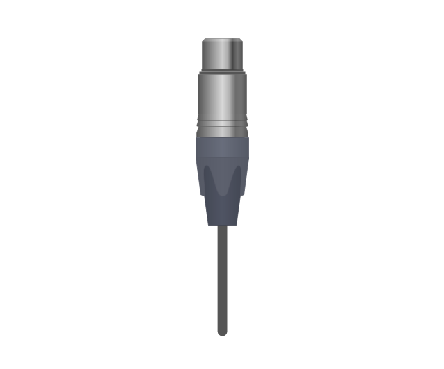
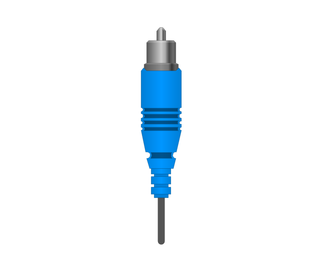
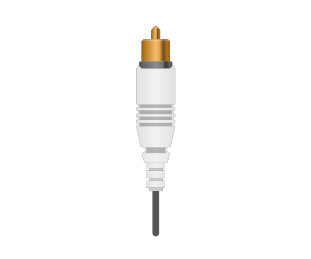
The vector stencils library "Audio and video connectors" contains 94 symbols of audio and video connectors and device silhouettes.
Use these jacks and plugs clipart icons for drawing hook up diagrams in the ConceptDraw PRO diagramming and vector drawing software extended with the Audio and Video Connectors solution from the Engineering area of ConceptDraw Solution Park.
www.conceptdraw.com/ solution-park/ engineering-audio-video-connectors
Device 1

Device 2

TV

Cable, thin

Cable, thick

Device 1, half part

Device 2, half part

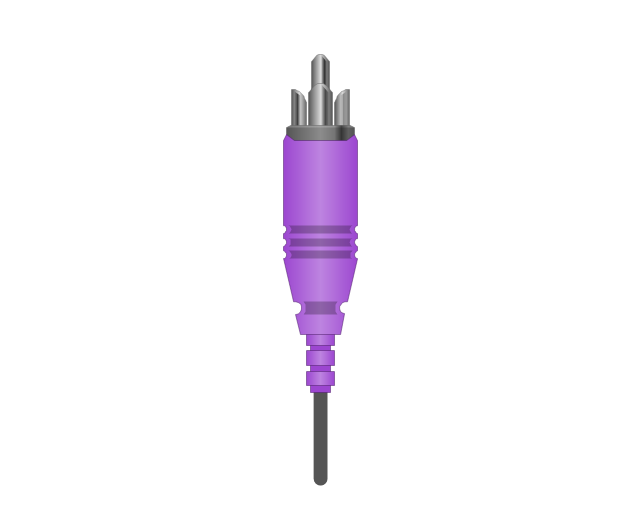
TRS plug, purple
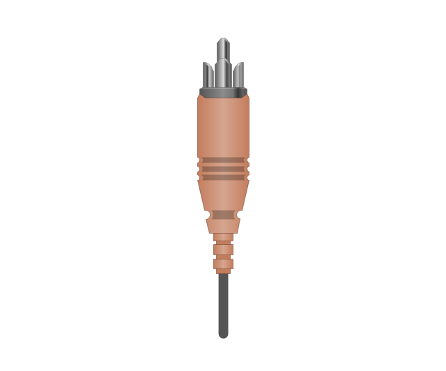
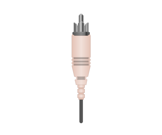
TRS plug, brown
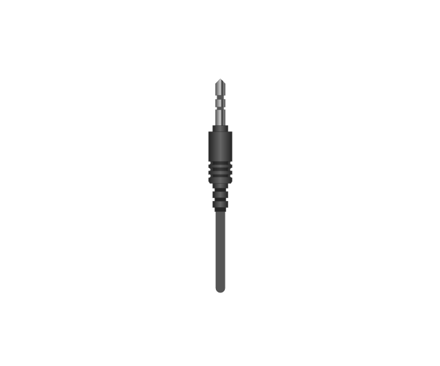
TRS plug, black

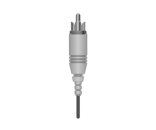
TRS plug, gray
TRS plug, blue
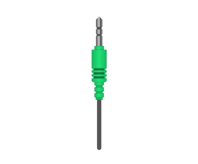
TRS plug, green
TRS jack, purple

TRS jack, brown

TRS jack, black

TRS jack, gray

TRS jack, blue

TRS jack, green

TRS plug, micro-jack
TRS, micro-jack

Headphone Mini Jack Cable
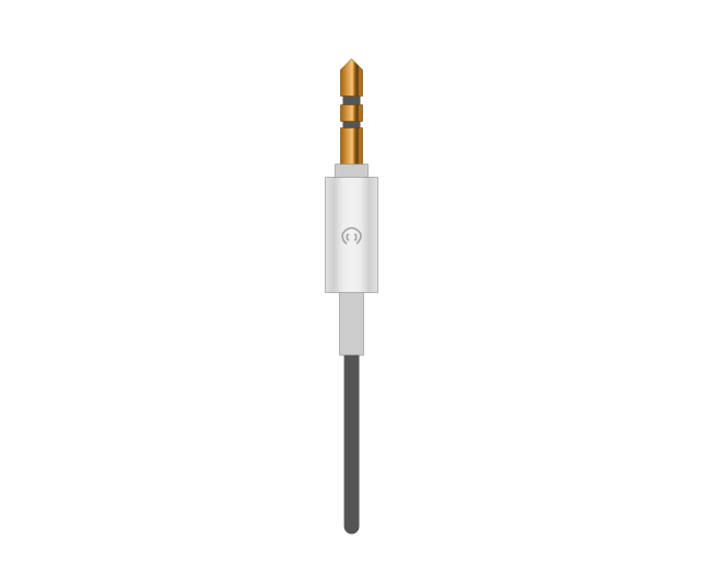
Headphone Mini Jack

Microphone Mini Jack Cable
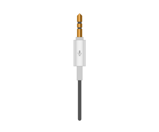
Microphone Mini Jack

XLR female Neutrik
XLR female Neutrik

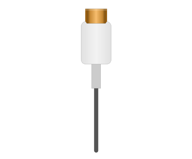
TOSLINK Optical Audio Cable, blue
TOSLINK Optical Audio Cable
TOSLINK Optical jack
TOSLINK Optical jack, blue

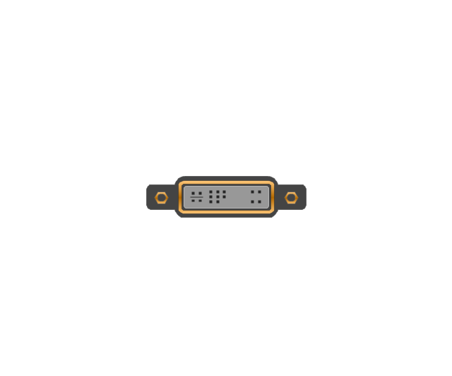
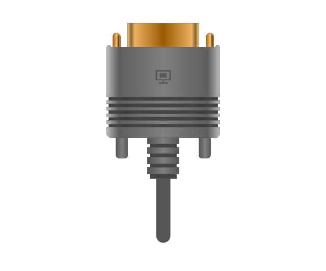
DVI plug
DVI-I (Single Link) jack
-jack-audio-and-video-connectors---vector-stencils-library.png--diagram-flowchart-example.png)
DVI-I (Dual Link) jack
-jack-audio-and-video-connectors---vector-stencils-library.png--diagram-flowchart-example.png)
DVI-D (Single Link) jack
-jack-audio-and-video-connectors---vector-stencils-library.png--diagram-flowchart-example.png)
DVI-D (Dual Link) jack
-jack-audio-and-video-connectors---vector-stencils-library.png--diagram-flowchart-example.png)
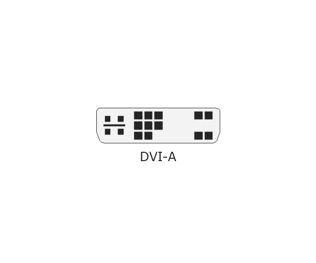
DVI-A Port
DVI-I (Single Link)
-audio-and-video-connectors---vector-stencils-library.png--diagram-flowchart-example.png)
DVI-I (Dual Link)
-audio-and-video-connectors---vector-stencils-library.png--diagram-flowchart-example.png)
DVI-D (Single Link)
-audio-and-video-connectors---vector-stencils-library.png--diagram-flowchart-example.png)
DVI-D (Dual Link)
-audio-and-video-connectors---vector-stencils-library.png--diagram-flowchart-example.png)
DVI-A
Mini DVI jack
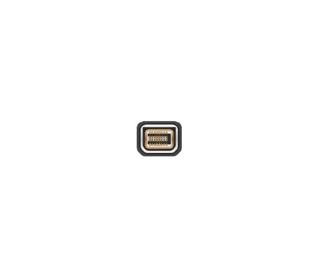
Mini DVI plug
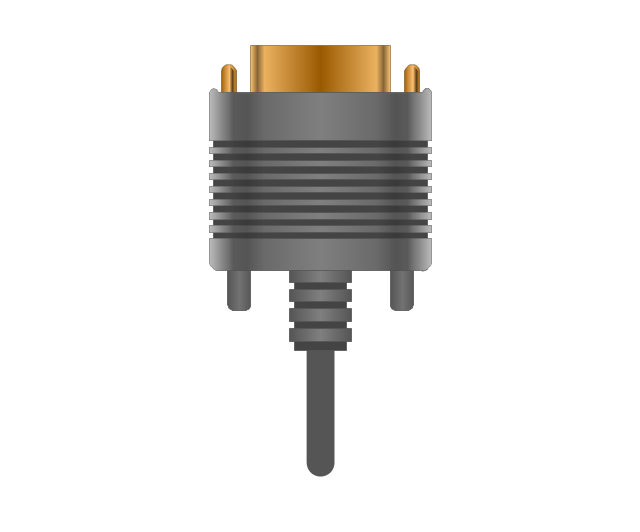
VGA plug
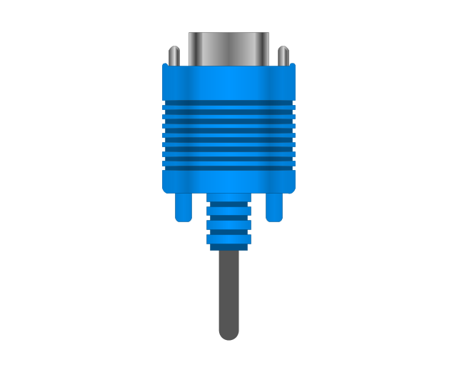
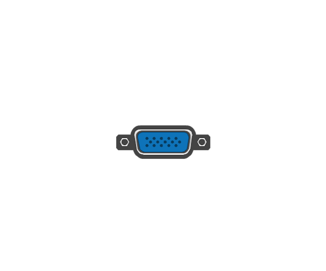
VGA jack
DFP jack
DFP plug
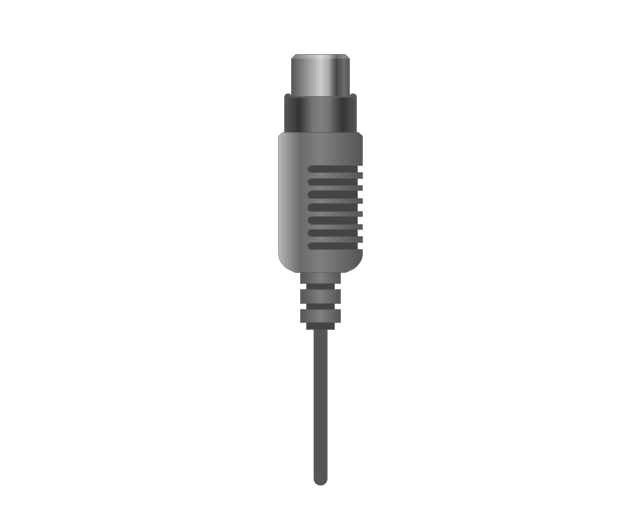
S-Video plug
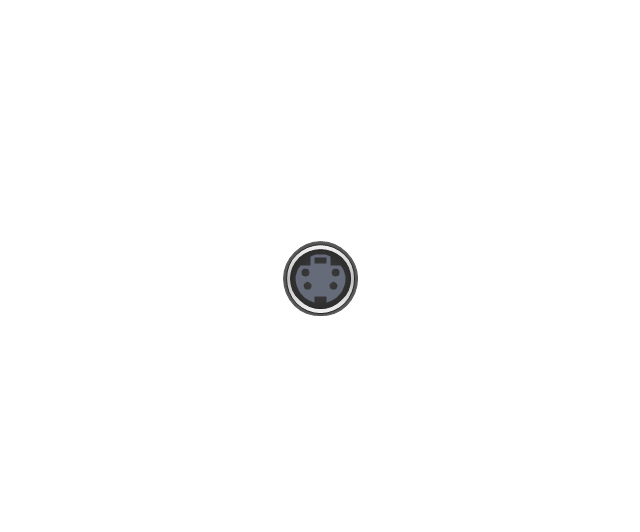
S-Video IN

S-Video OUT
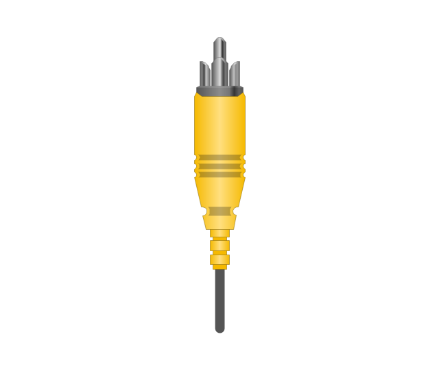
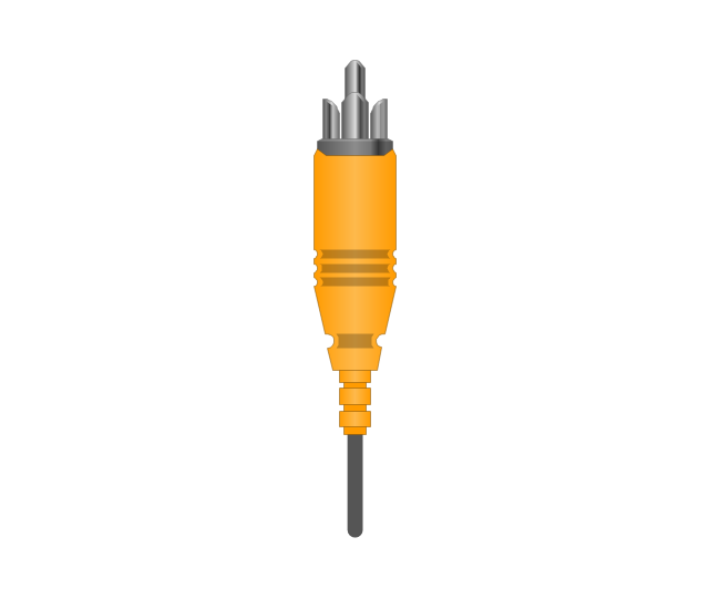
RCA, yellow

RCA, yellow
RCA, white

RCA, white
RCA, red

RCA, red

RCA, black

RCA, black
RCA, green

RCA, green
RCA, blue

RCA, blue
RCA, gray

RCA, gray
RCA, brown

RCA, brown
RCA, tan

RCA, tan
RCA, purple
RCA, purple

RCA, orange

RCA, orange
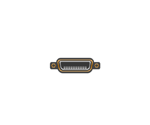
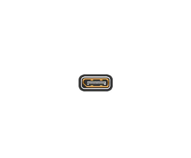
Display Port socket
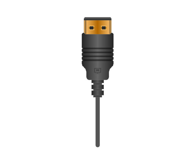
Display Port plug
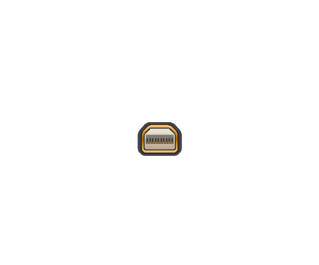
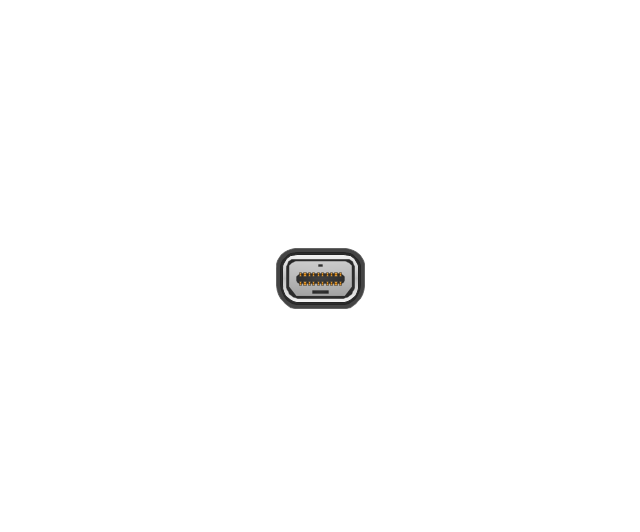
Mini Display port socket
Mini Display port socket, white

Mini Display port plug
Mini Display port plug, white
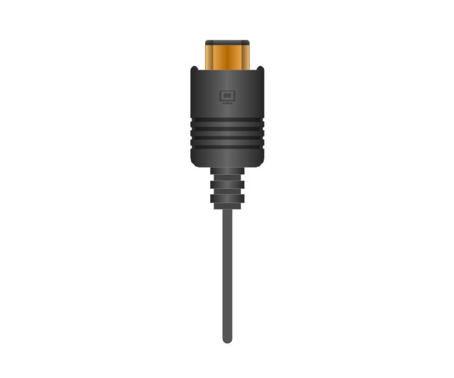
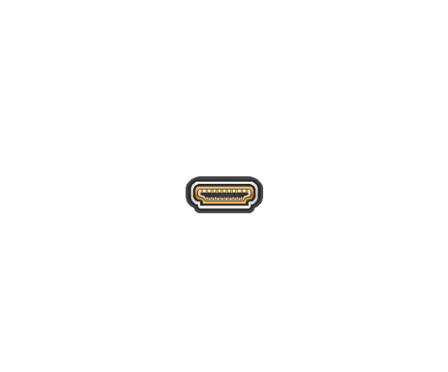
HDMI jack
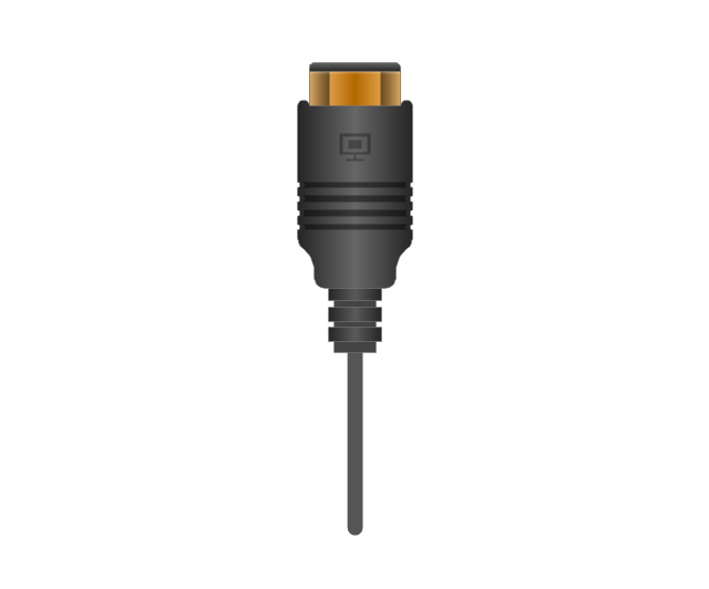
HDMI plug
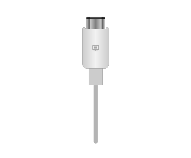
HDMI plug, white
Thunderbolt jack
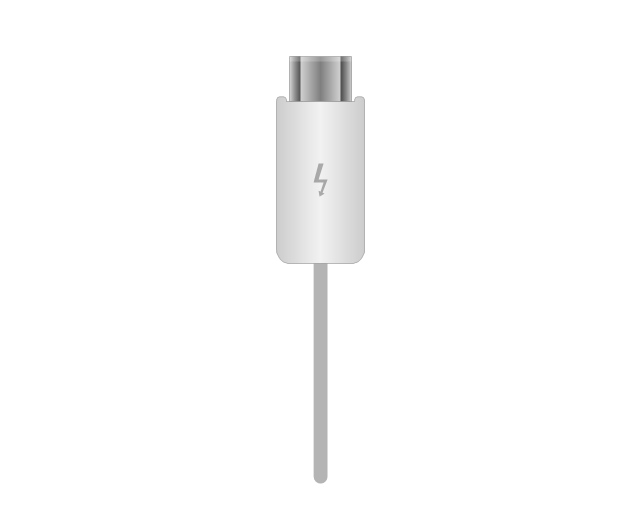
Thunderbolt plug
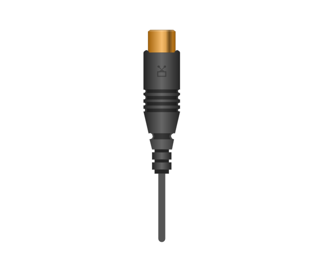
Coaxial TV plug
Coaxial TV jack

F connector jack

F connector plug
XLR male Neutrik

XLR male Neutrik
TS plug
TS jack

MIDI

MIDI
Standard Universal Audio & Video Connection Types

The vector stencils library "Electrical and telecom" contains 83 symbols of electrical and telecommunication equipment.
Use these shapes for drawing electrical and telecom system design floor plans, cabling layout schemes, and wiring diagrams in the ConceptDraw PRO diagramming and vector drawing software.
The vector stencils library "Electrical and telecom" is included in the Electric and Telecom Plans solution from the Building Plans area of ConceptDraw Solution Park.
Luminaire ceiling mount

Enclosed ceiling luminaire

Wall light

1-light bar

2-light bar

4-light bar

6-light bar

8-light bar

Down lighter

Outdoor lightning

Outdoor lightning, bollard

Batten fluorescent, 1 lamp

Batten fluorescent, 2 lamps

Batten fluorescent, 3 lamps

Batten fluorescent, 4 lamps

Surface Fluorescent Light

Modular fluorescent fitting

Modular fluorescent fitting, inverter

Modular fluorescent fitting 2

Pull-cord switch

Emergency light

Emergency light 2

Emergency sign

Switch

Switch, 1 pole

Switch, 2 pole

Switch, 2-way

Multi-switch

Switch, intermediate

Dimmer switch

Dimmer switch 2

Socket

Socket 2

Switched socket

Switched socket 2

Double socket

Double socket 2

Socket outlet

Telephone outlet

Telephone outlet 2

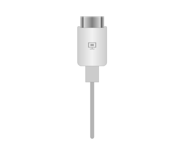
Stereo outlet

Television outlet

Service panel, surface

Service panel, inset

Thermostat

Ceiling fan

Hold open unit

Detector

Fire alarm

City Fire Alarm Station

Fire Alarm Station

Fire Alarm Bell

Fire Alarm Central Station

Automatic Fire Alarm Device

Main control

Ground

Doorbell

Push Button

Buzzer

Annunciator

Horn

Maid's Signal Plug

Signal Central Station

Doorbell Chime

Doorbell Transformer

Magnetic Door Hold

Intercom

Telephone Key System

Digital Satellite System

Inside Antenna

Outside Antenna

Electric Motors

Single Phase

Three of Poly Phase

Wall Mounted Electrical Junction Box for Hardware

Wall Mounted Telephone/Data Junction Box for Hardware

Card Reader Access System

Emergency Release Button

Motion Sensor

Electric Door Opener

Watchman's Station

Watchman's Central Station

Battery

- Power socket outlet layout | Electrical and Telecom Plan Software ...
- General Symbol For Socket Outlet
- Types Of Single Phase Socket Outlet Symbol Types Of Single Phase
- Symbols Sockets Switches
- Socket Outlet Symbol Iec
- Electrical Symbol For Cooker Socket
- Computer Network Diagrams | Symbols Cooker Switch Socket
- Symbol Of Switched Socket Off
- Show A Symbol Of Cooker Socket Unit
- Electrical Symbol For Cooker Control With Socket Outlet
- Hotel Plan. Hotel Plan Examples | Symbol Of Air Conditioner Socket
- Electrical Symbol For Double Socket Outlet
- Three Phase Industrial Socket Outlet Symbol
- Power socket outlet layout | Electrical Symbols — Lamps, Acoustics ...
- Cooker Control Socket Outlet Symbol
- Electrical Symbols — Terminals and Connectors | How To use ...
- Power socket outlet layout | Floot Symbol
- How To use House Electrical Plan Software | Socket Outlet Symbol ...
- Internet Socket Wall Mounted General Symbol
- Symbols Of Television Socket Outlet