Basic Flowchart Symbols and Meaning


Mathematics Symbols

 Mathematics
Mathematics solution extends ConceptDraw PRO software with templates, samples and libraries of vector stencils for drawing the mathematical illustrations, diagrams and charts.
Mathematical Diagrams

The vector stencils library "Bank UML profile diagram" contains 9 shapes for drawing UML profile diagrams.
Use it for object-oriented modeling of your bank information system.
"A profile diagram operates at the metamodel level to show stereotypes as classes with the <> stereotype, and profiles as packages with the <> stereotype. The extension relation (solid line with closed, filled arrowhead) indicates what metamodel element a given stereotype is extending." [Profile diagram. Wikipedia]
This example of UML profile diagram symbols for the ConceptDraw PRO diagramming and vector drawing software is included in the ATM UML Diagrams solution from the Software Development area of ConceptDraw Solution Park.
Use it for object-oriented modeling of your bank information system.
"A profile diagram operates at the metamodel level to show stereotypes as classes with the <
This example of UML profile diagram symbols for the ConceptDraw PRO diagramming and vector drawing software is included in the ATM UML Diagrams solution from the Software Development area of ConceptDraw Solution Park.
UML profile diagram symbols

Scientific Symbols Chart

Mathematics Solution from the Science and Education area of ConceptDraw Solution Park includes a few shape libraries of plane, solid geometric figures, trigonometrical functions and greek letters to help you create different professional looking mathematic illustrations for science and education.
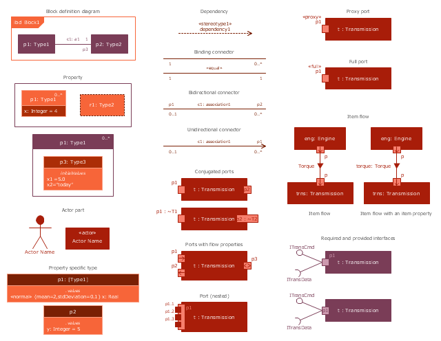
The vector stencils library "Internal block diagram" contains 22 SysML symbols.
Use it to design your internal block diagrams using ConceptDraw PRO diagramming and vector drawing software.
"Internal Block Diagram
An internal block diagram is based on the UML composite structure diagram, with restrictions and extensions as defined
by SysML. ...
Property types
Four general categories of properties of blocks are recognized in SysML: parts, references, value properties, and
constraint properties. ... A part or value property is always shown on an internal block diagram with a solid-outline box. A reference property is shown by a dashed-outline box, consistent with UML. Ports are special cases of properties, and have a variety of notations... Constraint properties and their parameters also have their own notations... " [www.omg.org/ spec/ SysML/ 1.3/ PDF]
The SysML shapes example "Design elements - Internal block diagram" is included in the SysML solution from the Software Development area of ConceptDraw Solution Park.
Internal block diagram symbols
Types of Welding in Flowchart

The vector stencils library "Bank UML sequence diagram" contains 34 shapes for drawing UML sequence diagrams.
Use it for object-oriented modeling of your bank information system.
"A sequence diagram shows, as parallel vertical lines (lifelines), different processes or objects that live simultaneously, and, as horizontal arrows, the messages exchanged between them, in the order in which they occur. This allows the specification of simple runtime scenarios in a graphical manner.
Diagram building blocks.
If the lifeline is that of an object, it demonstrates a role. Leaving the instance name blank can represent anonymous and unnamed instances.
Messages, written with horizontal arrows with the message name written above them, display interaction. Solid arrow heads represent synchronous calls, open arrow heads represent asynchronous messages, and dashed lines represent reply messages. ...
Activation boxes, or method-call boxes, are opaque rectangles drawn on top of lifelines to represent that processes are being performed in response to the message (ExecutionSpecifications in UML).
Objects calling methods on themselves use messages and add new activation boxes on top of any others to indicate a further level of processing.
When an object is destroyed (removed from memory), an X is drawn on top of the lifeline, and the dashed line ceases to be drawn below it ...
A message sent from outside the diagram can be represented by a message originating from a filled-in circle (found message in UML) or from a border of the sequence diagram (gate in UML)." [Sequence diagram. Wikipedia]
This example of UML sequence diagram symbols for the ConceptDraw PRO diagramming and vector drawing software is included in the ATM UML Diagrams solution from the Software Development area of ConceptDraw Solution Park.
UML sequence diagram symbols

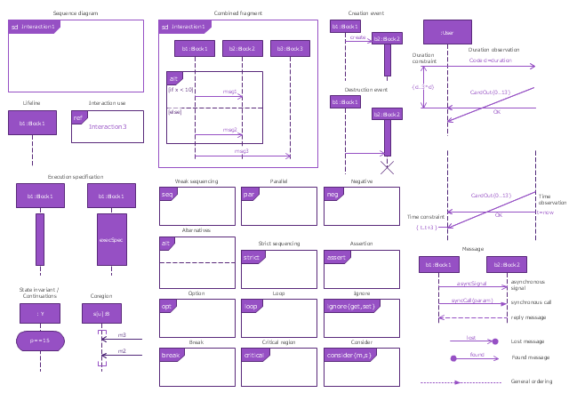
The vector stencils library "Sequence diagram" contains 32 SysML symbols.
Use it to design your sequence diagrams using ConceptDraw PRO diagramming and vector drawing software.
"A sequence diagram shows, as parallel vertical lines (lifelines), different processes or objects that live simultaneously, and, as horizontal arrows, the messages exchanged between them, in the order in which they occur. This allows the specification of simple runtime scenarios in a graphical manner. ...
If the lifeline is that of an object, it demonstrates a role. Leaving the instance name blank can represent anonymous and unnamed instances.
Messages, written with horizontal arrows with the message name written above them, display interaction. Solid arrow heads represent synchronous calls, open arrow heads represent asynchronous messages, and dashed lines represent reply messages. If a caller sends a synchronous message, it must wait until the message is done, such as invoking a subroutine. If a caller sends an asynchronous message, it can continue processing and doesn’t have to wait for a response. Asynchronous calls are present in multithreaded applications and in message-oriented middleware. Activation boxes, or method-call boxes, are opaque rectangles drawn on top of lifelines to represent that processes are being performed in response to the message (ExecutionSpecifications in UML).
Objects calling methods on themselves use messages and add new activation boxes on top of any others to indicate a further level of processing.
When an object is destroyed (removed from memory), an X is drawn on top of the lifeline, and the dashed line ceases to be drawn below it (this is not the case in the first example though). It should be the result of a message, either from the object itself, or another.
A message sent from outside the diagram can be represented by a message originating from a filled-in circle (found message in UML) or from a border of the sequence diagram (gate in UML)." [Sequence diagram. Wikipedia]
The SysML shapes example "Design elements - Sequence diagram" is included in the SysML solution from the Software Development area of ConceptDraw Solution Park.
SysML sequence diagram symbols
Process Flow Chart Symbols

Bubble diagrams with ConceptDraw PRO

Basic Diagramming


HelpDesk
How to Draw Geometric Shapes in ConceptDraw PRO

- Mathematical Diagrams | Basic Flowchart Symbols and Meaning ...
- Design elements - Solid geometry | Basic Flowchart Symbols and ...
- Mathematics | Mathematical Diagrams | Mathematics Symbols ...
- Mathematical Diagrams | Mathematics | Mathematics Symbols ...
- Scientific Symbols Chart | Mathematics Symbols | Mathematics ...
- Mathematical Diagrams | Mathematics Symbols | Mathematics ...
- Mathematics | Design elements - Solid geometry | Mathematics ...
- Solid Shape Diagram
- Scientific Symbols Chart | Solid geometry - Vector stencils library ...
- Mathematics | Design elements - Solid geometry | Mathematics ...
- Mathematics | Mathematics Symbols | Mathematical Diagrams ...
- Mathematics | Mathematics Symbols | Mathematical Diagrams ...
- Electrical Schematic Symbols | Electrical Diagram Symbols | Wiring ...
- Mathematics Symbols | Plane geometry - Vector stencils library ...
- Symbol Of Solid Figure
- Geometry Diagrams
- Mathematical Diagrams | Math illustrations - Template | Mathematics ...
- Design elements - Solid geometry | Mathematics Symbols | Scientific ...
- Mathematics Symbols | Scientific Symbols Chart | Mathematics ...
- All Kinds Of Solid Geometry