Software Defined Networking System Overview


Cisco People. Cisco icons, shapes, stencils and symbols

GHS Labels Meanings

Virtual networks. Computer and Network Examples

Azure Management

Easy Flowchart Program and Standard Flowchart Symbols

Star Network Topology


Network Topologies

Diagramming software for Amazon Web Service icon set: Networking and Content Delivery
 Cisco Networking
Cisco Networking solution extends the ConceptDraw DIAGRAM software functionality with properties of network diagramming and network modeling software. Solution provides the multifarious samples and large quantity of libraries with incredibly huge amount of complex predesigned vector design elements of standardized Cisco devices and equipment, such as CISCO servers, Cisco switches, Cisco Fabric Interconnects, Cisco Gateways, Access Servers, Cisco Optical NCS 1000, Cisco Optical NCS 2000, Cisco Optical NCS 4000, and Cisco Optical NCS 4200 devices, Cisco Physical Security, Cisco Service Exchange, Cisco Storage Networking, Cisco Unified Communications, Cisco Video, Cisco Wireless, and Cisco Application Networking Services equipment.
 Computer and Networks Area
The solutions from Computer and Networks Area of ConceptDraw Solution Park collect samples, templates and vector stencils libraries for drawing computer and network diagrams, schemes and technical drawings.
"In computer networks, networked computing devices pass data to each other along data connections. The connections (network links) between nodes are established using either cable media or wireless media. ...
Network computer devices that originate, route and terminate the data are called network nodes. Nodes can include hosts such as personal computers, phones, servers as well as networking hardware. ...
Network links.
The communication media used to link devices to form a computer network include electrical cable (HomePNA, power line communication, G.hn), optical fiber (fiber-optic communication), and radio waves (wireless networking). In the OSI model, these are defined at layers 1 and 2 - the physical layer and the data link layer.
A widely adopted family of communication media used in local area network (LAN) technology is collectively known as Ethernet. The media and protocol standards that enable communication between networked devices over Ethernet are defined by IEEE 802.3. Ethernet transmit data over both copper and fiber cables. Wireless LAN standards (e.g. those defined by IEEE 802.11) use radio waves, or others use infrared signals as a transmission medium. Power line communication uses a building's power cabling to transmit data. ...
Network nodes.
Apart from the physical communications media described above, networks comprise additional basic system building blocks, such as network interface controller (NICs), repeaters, hubs, bridges, switches, routers, modems, and firewalls." [Computer network. Wikipedia]
The network equipment and cabling layout floorplan template for the ConceptDraw PRO diagramming and vector drawing software is included in the Network Layout Floor Plans solution from the Computer and Networks area of ConceptDraw Solution Park.
LAN equipment and cabling layout floorplan template

SDL — Systems Engineering

 Computer Network Diagrams
Computer Network Diagrams solution extends ConceptDraw DIAGRAM software with samples, templates and libraries of vector icons and objects of computer network devices and network components to help you create professional-looking Computer Network Diagrams, to plan simple home networks and complex computer network configurations for large buildings, to represent their schemes in a comprehensible graphical view, to document computer networks configurations, to depict the interactions between network's components, the used protocols and topologies, to represent physical and logical network structures, to compare visually different topologies and to depict their combinations, to represent in details the network structure with help of schemes, to study and analyze the network configurations, to communicate effectively to engineers, stakeholders and end-users, to track network working and troubleshoot, if necessary.
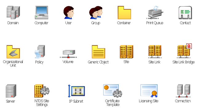
The vector stencils library "Active Directory" contains 20 symbols of Active Directory objects for drawing AD network diagrams. It helps network and system administrators to visualize Microsoft Windows Active Directory structures for network design, installation and maintainance.
"Objects.
An Active Directory structure is an arrangement of information about objects. The objects fall into two broad categories: resources (e.g., printers) and security principals (user or computer accounts and groups). Security principals are assigned unique security identifiers (SIDs).
Each object represents a single entity - whether a user, a computer, a printer, or a group - and its attributes. Certain objects can contain other objects. An object is uniquely identified by its name and has a set of attributes - the characteristics and information that the object represents - defined by a schema, which also determines the kinds of objects that can be stored in Active Directory.
The schema object lets administrators extend or modify the schema when necessary. However, because each schema object is integral to the definition of Active Directory objects, deactivating or changing these objects can fundamentally change or disrupt a deployment. Schema changes automatically propagate throughout the system. Once created, an object can only be deactivated - not deleted. Changing the schema usually requires planning. Sites are implemented as a set of well-connected subnets." [Active Directory. Wikipedia]
The shapes example "Design elements - Active Directory" was created using the ConceptDraw PRO diagramming and vector drawing software extended with the Active Directory Diagrams solution from the Computer and Networks area of ConceptDraw Solution Park.
Active Directory symbols
What is Electrical Engineering? Basic Electrical Engineering Software

 Rapid UML
In order to create any of the described drawings, the ConceptDraw DIAGRAM vector diagramming and drawing software can be used. Having the Rapid UML solution that extends the ConceptDraw DIAGRAM application with the ability to develop the needed UML diagrams within a short period of time, can help you complete the UML-related tasks faster. This solution uses the so-called “ConceptDraw RapidDraw” techniques and it may be useful for many different IT specialists, programmers, software developers, software engineers.
Network Visualization Guide.How to Use ConceptDraw Network Visualization Tool

Product Overview

- Software Defined Networking System Overview | Venn Diagrams ...
- Software Defined Networking System Overview | Call center network ...
- Software Defined Networking System Overview ...
- Software Defined Networking System Overview | Cisco Network ...
- Software Defined Networking System Overview | Interaction ...
- Network Protocols | Software Defined Networking System Overview ...
- Software Defined Networking System Overview | Design A Lan ...
- Software Defined Networking System Overview | Intelligent Services ...
- Intelligent transportation system | Software Defined Networking ...