How To use House Electrical Plan Software


Interior Design Piping Plan - Design Elements

Home Electrical Plan

The vector stencils library "Pipes 1" contains 28 symbols of pipes. Use it for drawing plumbing and piping building plans, schematic diagrams, blueprints, or technical drawings of waste water disposal systems, hot and cold water supply systems in the ConceptDraw PRO diagramming and vector drawing software extended with the Plumbing and Piping Plans solution from the Building Plans area of ConceptDraw Solution Park.
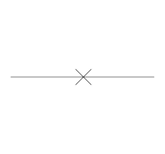
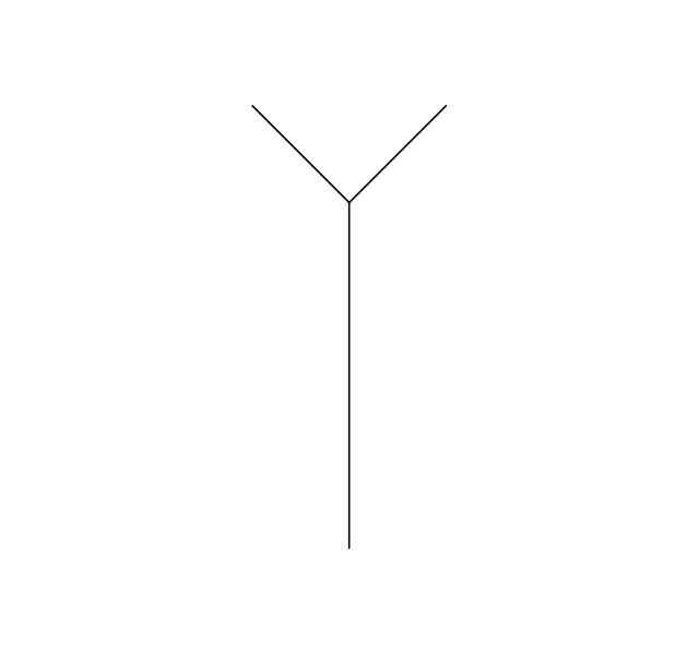
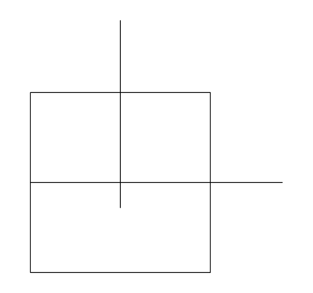
General joint

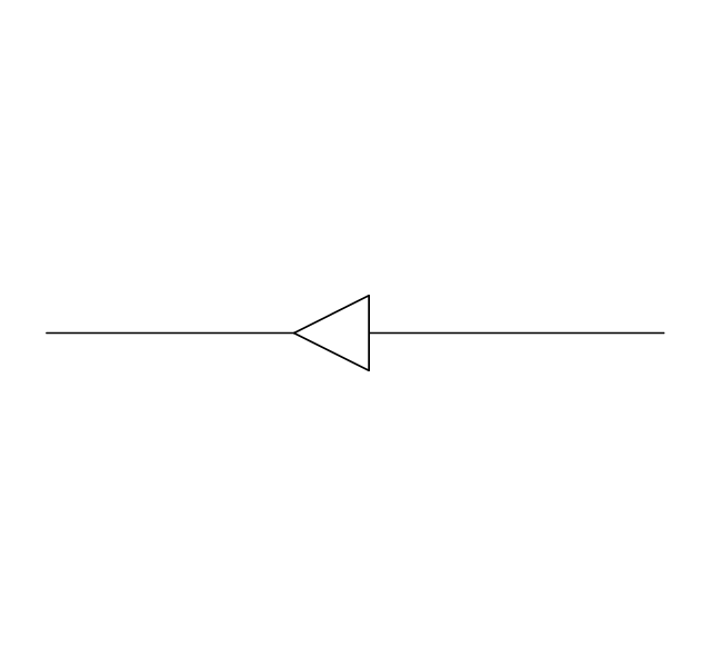
Butt weld
Soldered / solvent
Screwed joint
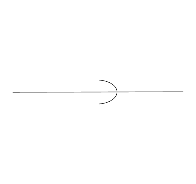
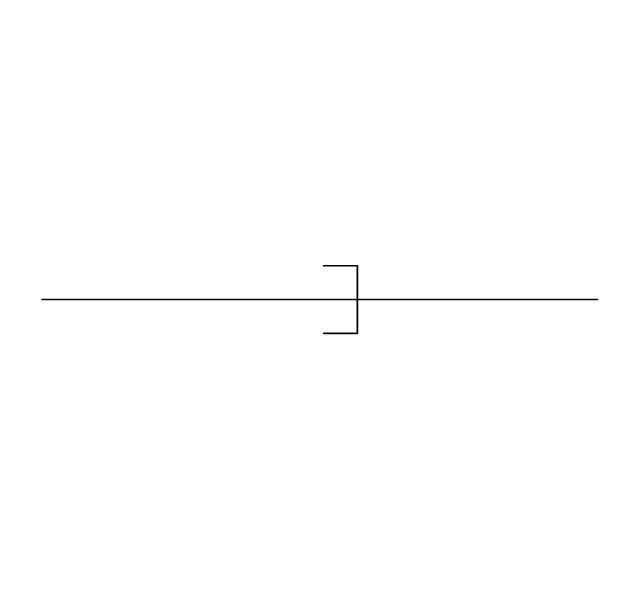
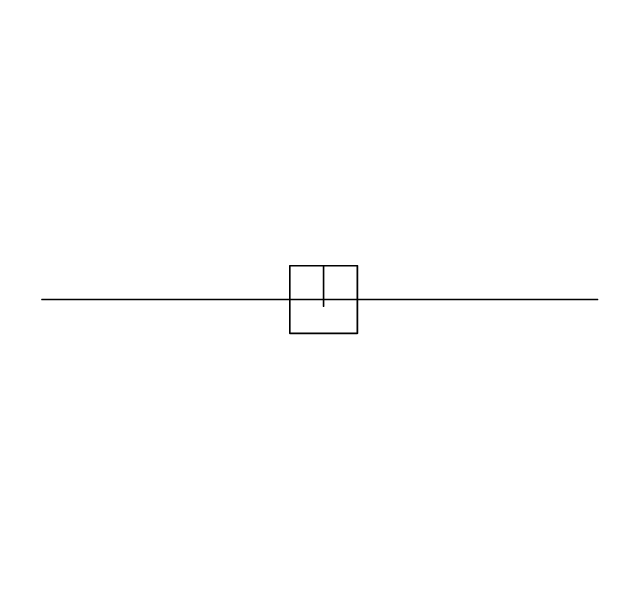
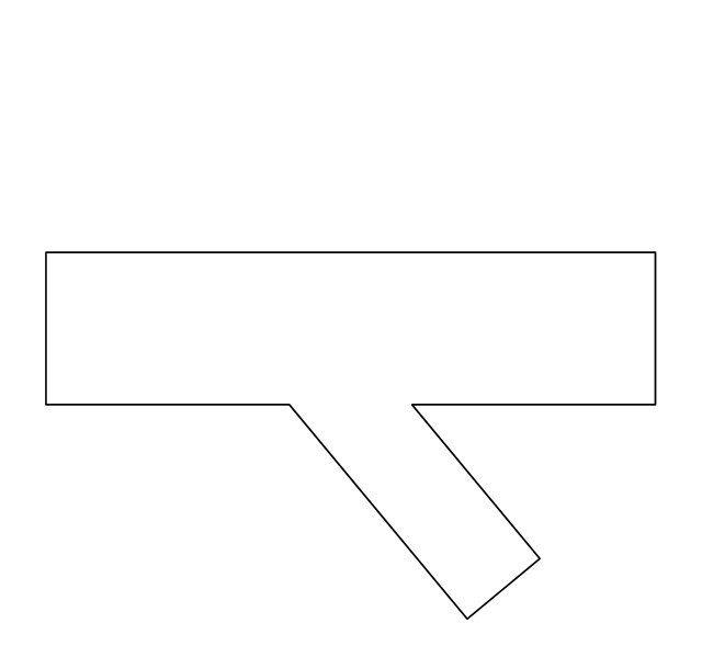
Socket and spigot
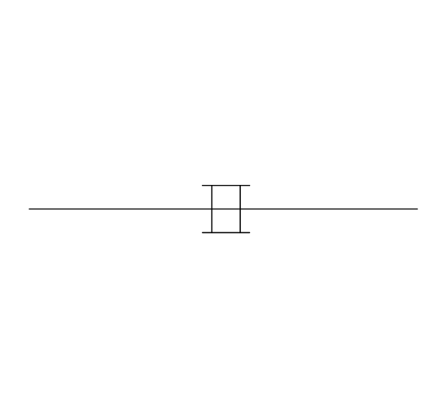
Sleeve joint
Socket weld
Flanged / bolted

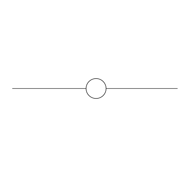
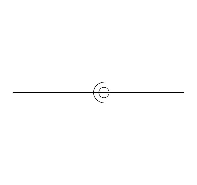
Swivel joint
Electrically bonded
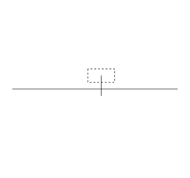
Electrically insulated

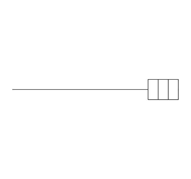
End caps 1
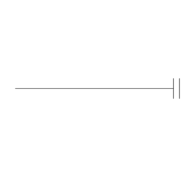
End caps 2

End caps 3
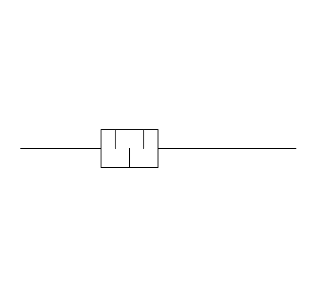
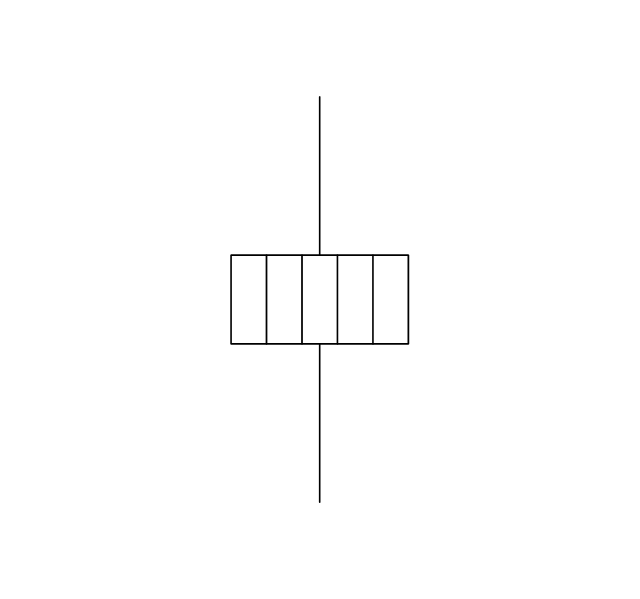
Strainer

Separator
Exhaust silencer
Drain silencer
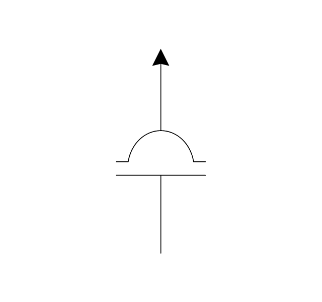
Open vent
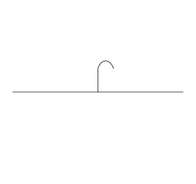
Syphon drain

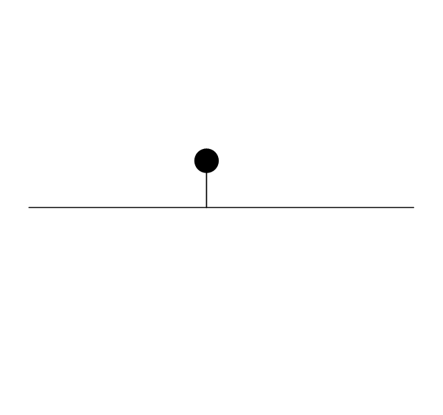
Hydrant
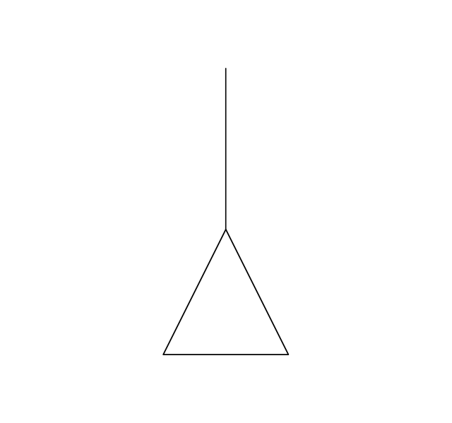
Tundish
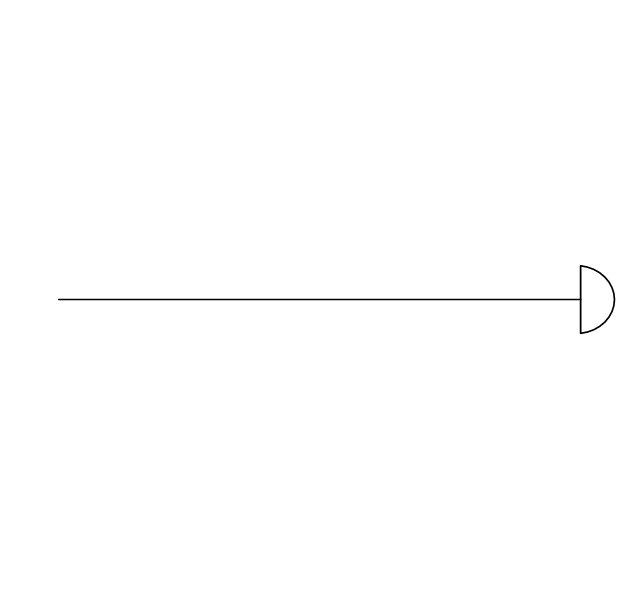
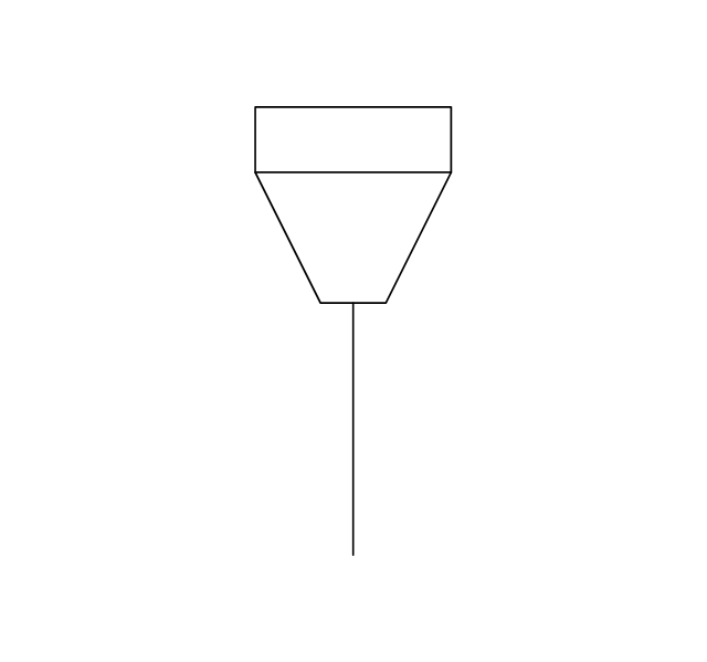
Bell mouth
Exhaust head
Bursting disc
Flame arrester
Y strainer
Liquid seal open/closed
Electrical Symbols, Electrical Diagram Symbols

Electrical and Telecom Plan Software

Electrical Symbols — Thermo

Electrical Diagram Software

Electrical Symbols — MOSFET

Audio and Video Connections Explained

- Plumbing and Piping Plans | Image Of Plumbing Layout Of Building
- Symbol For Swiches And Sockets
- Electrical Component Of Socket
- Picture Graphs | Technical Electrical Image
- How To use House Electrical Plan Software | Socket Outlet Symbol ...
- Power socket outlet layout | Mechanical Engineering | Plumbing and ...
- Twin Socket Symbol
- Power socket outlet layout
- Network Glossary Definition | Jack Plug And Jack Socket Electrical ...
- Network Glossary Definition | Symbol Of Electrical Socket 5 In One