How To Draw Building Plans


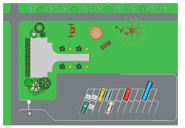
This site layout plan sample depicts the landscape architecture of outdoor area including playground and parking.
"Landscape architecture is the design of outdoor public areas, landmarks, and structures to achieve environmental, social-behavioral, or aesthetic outcomes. It involves the systematic investigation of existing social, ecological, and geological conditions and processes in the landscape, and the design of interventions that will produce the desired outcome. The scope of the profession includes: urban design; site planning; stormwater management; town or urban planning; environmental restoration; parks and recreation planning; visual resource management; green infrastructure planning and provision; and private estate and residence landscape master planning and design; all at varying scales of design, planning and management. A practitioner in the profession of landscape architecture is called a landscape architect." [Landscape architecture. Wikipedia]
The landscape design example "Site layout plan" was created using the ConceptDraw PRO diagramming and vector drawing software extended with the Site Plans solution from the Building Plans area of ConceptDraw Solution Park.
Landscape design
Building Drawing Software for Design Site Plan

UML Use Case Diagrams


 Plumbing and Piping Plans
Plumbing and Piping Plans solution extends ConceptDraw PRO v10.2.2 software with samples, templates and libraries of pipes, plumbing, and valves design elements for developing of water and plumbing systems, and for drawing Plumbing plan, Piping plan, PVC Pipe plan, PVC Pipe furniture plan, Plumbing layout plan, Plumbing floor plan, Half pipe plans, Pipe bender plans.
Network Diagram Software LAN Network Diagrams & Diagrams for LAN Physical Office Network Diagrams


HelpDesk
How to Create a Floor Plan

Electrical Symbols, Electrical Diagram Symbols

 Fishbone Diagrams
The Fishbone Diagrams solution extends ConceptDraw PRO v10 software with the ability to easily draw the Fishbone Diagrams (Ishikawa Diagrams) to clearly see the cause and effect analysis and also problem solving. The vector graphic diagrams produced using this solution can be used in whitepapers, presentations, datasheets, posters, and published technical material.
Example of DFD for Online Store (Data Flow Diagram) DFD Example


 Social Media Response
This solution extends ConceptDraw DIAGRAM and ConceptDraw MINDMAP with the ability to draw interactive flow charts with action mind map templates, to help create an effective response to applicable social media mentions.
Home Electrical Plan

 Basic Divided Bar Diagrams
This solution extends the capabilities of ConceptDraw PRO v10.3.0 (or later) with templates, samples and a library of vector stencils for drawing Divided Bar diagrams.
 Aerospace and Transport
This solution extends ConceptDraw PRO software with templates, samples and library of vector clipart for drawing the Aerospace and Transport Illustrations. It contains clipart of aerospace objects and transportation vehicles, office buildings and anci
 Directional Maps
Directional Maps solution extends ConceptDraw PRO software with templates, samples and libraries of vector stencils for drawing the directional, location, site, transit, road and route maps, plans and schemes.
- Site layout plan | Landscape Design Drawings | Building Drawing ...
- Estate Site Layout Design
- Site Layout Plan Of A Building Estate
- How To Draw Building Plans | Site layout plan | Building Drawing ...
- How To Draw Building Plans | Site layout plan | Building Drawing ...
- Estate Site Layout
- Estate Planning Software
- Security Sketch Of An Estate With Diagram
- Site Plan Layout Of An Estate
- Estate Design Layout
- Site layout plan | Fire Exit Plan. Building Plan Examples ...
- Example Of An Estate Landscape Plan
- Example Of An Estate Building Plan
- Estate Building Site Plan
- Example Site Layout Plan
- Building Drawing Software for Design Site Plan | How To Draw ...
- Site layout plan | Building Drawing Design Element Site Plan ...
- Site layout plan | Building Drawing Design Element Site Plan ...
- Sample Of A Site Layout
- The Types Of Site Layout For Estate