 Mechanical Engineering
This solution extends ConceptDraw DIAGRAM.9 mechanical drawing software (or later) with samples of mechanical drawing symbols, templates and libraries of design elements, for help when drafting mechanical engineering drawings, or parts, assembly, pneumatic,
Mechanical Drawing Symbols

Mechanical Engineering

The vector stencils library "Pneumatic pumps and motors" contains 39 symbols of pneumatic pumps, motors and pump-motors for designing the engineering drawings of pneumatic circuits.
"A pneumatic motor or compressed air engine is a type of motor which does mechanical work by expanding compressed air. Pneumatic motors generally convert the compressed air energy to mechanical work through either linear or rotary motion. Linear motion can come from either a diaphragm or piston actuator, while rotary motion is supplied by either a vane type air motor or piston air motor." [Pneumatic motor. Wikipedia]
"A gas compressor is a mechanical device that increases the pressure of a gas by reducing its volume. An air compressor is a specific type of gas compressor.
Compressors are similar to pumps: both increase the pressure on a fluid and both can transport the fluid through a pipe. As gases are compressible, the compressor also reduces the volume of a gas. Liquids are relatively incompressible; while some can be compressed, the main action of a pump is to pressurize and transport liquids." [Gas compressor. Wikipedia]
The shapes example "Design elements - Pneumatic pumps and motors" was created using the ConceptDraw PRO diagramming and vector drawing software extended with the Mechanical Engineering solution from the Engineering area of ConceptDraw Solution Park.
Pneumatic pump and motor symbols

The vector stencils library "Hydraulic pumps and motors" contains 74 symbols of hydraulic pump vector stencils, hydraulic motor symbols for engineering drawings of fluid power and hydraulic control systems.
"Hydraulic pumps are used in hydraulic drive systems and can be hydrostatic or hydrodynamic.
Hydrostatic pumps are positive displacement pumps while hydrodynamic pumps can be fixed displacement pumps, in which the displacement (flow through the pump per rotation of the pump) cannot be adjusted, or variable displacement pumps, which have a more complicated construction that allows the displacement to be adjusted." [Hydraulic pump. Wikipedia]
"A hydraulic motor is a mechanical actuator that converts hydraulic pressure and flow into torque and angular displacement (rotation). The hydraulic motor is the rotary counterpart of the hydraulic cylinder.
Conceptually, a hydraulic motor should be interchangeable with a hydraulic pump because it performs the opposite function - much as the conceptual DC electric motor is interchangeable with a DC electrical generator. However, most hydraulic pumps cannot be used as hydraulic motors because they cannot be backdriven. Also, a hydraulic motor is usually designed for the working pressure at both sides of the motor.
Hydraulic pumps, motors, and cylinders can be combined into hydraulic drive systems. One or more hydraulic pumps, coupled to one or more hydraulic motors, constitutes a hydraulic transmission." [Hydraulic motor. Wikipedia]
The shapes example "Design elements - Hydraulic pumps and motors" was created using the ConceptDraw PRO diagramming and vector drawing software extended with the Mechanical Engineering solution from the Engineering area of ConceptDraw Solution Park.
Hydraulic pump and motor symbols

The vector stencils library "Hydraulic pumps and motors" contains 74 symbols of hydraulic equipment.
Use these shapes for engineering drawings of fluid power and hydraulic control systems in the ConceptDraw PRO diagramming and vector drawing software extended with the Mechanical Engineering solution from the Engineering area of ConceptDraw Solution Park.
www.conceptdraw.com/ solution-park/ engineering-mechanical
Pump, hydraulic

Motor, hydraulic
Pump-motor, hydraulic
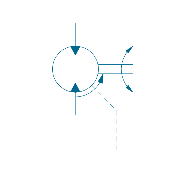
Pump, fixed, external drain
Pump, fixed, external drain
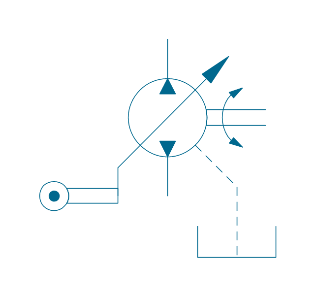
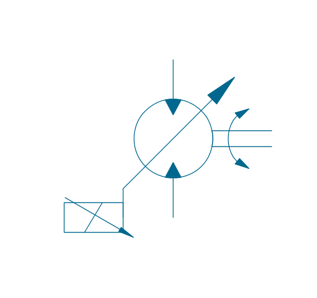
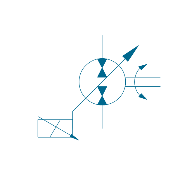
Pump, variable
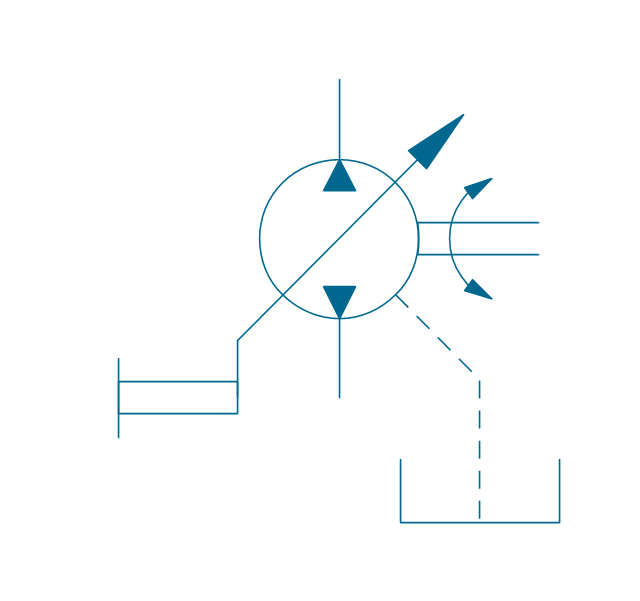
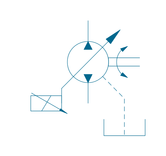
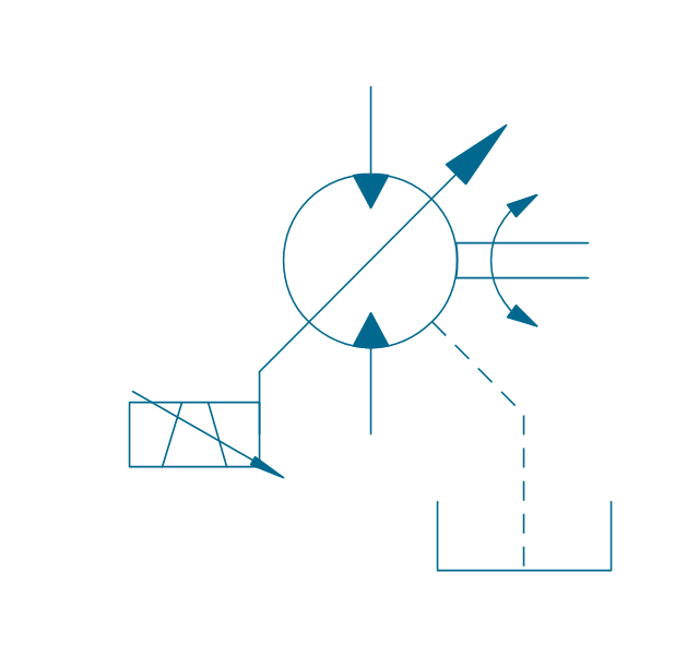
Pump, variable, external drain

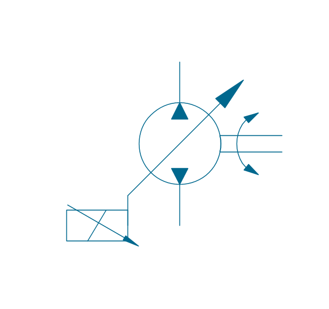
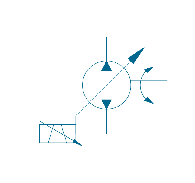
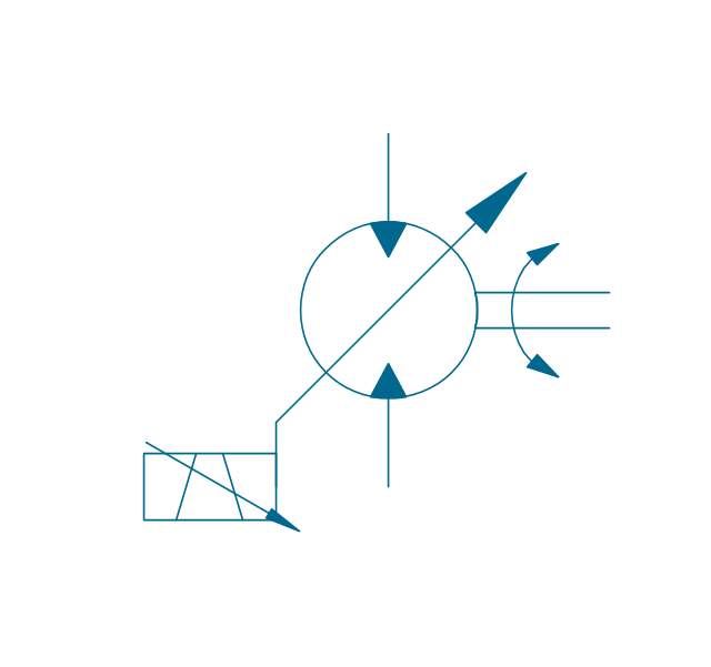
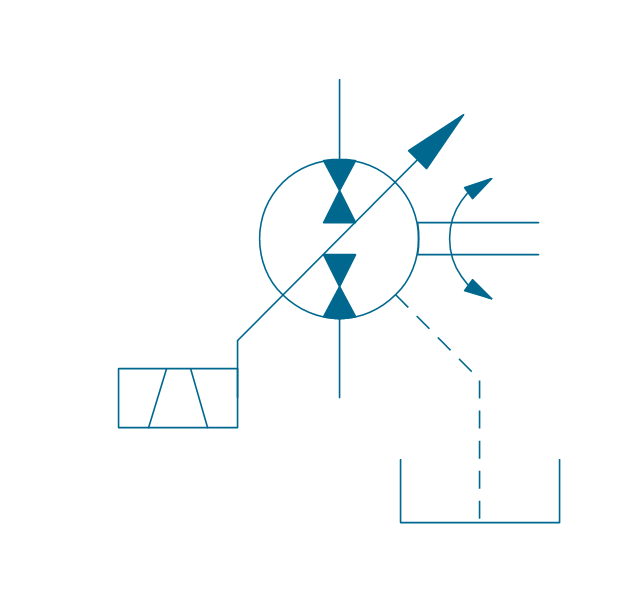
Pump, var., manual override

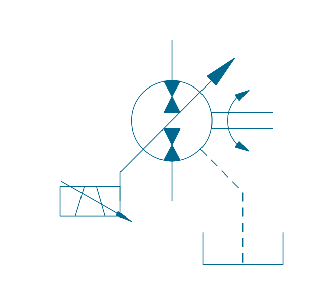
Pump, var., manual override, drain
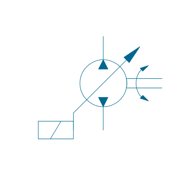
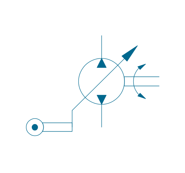
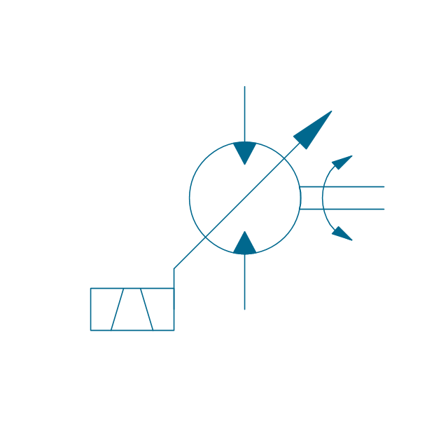
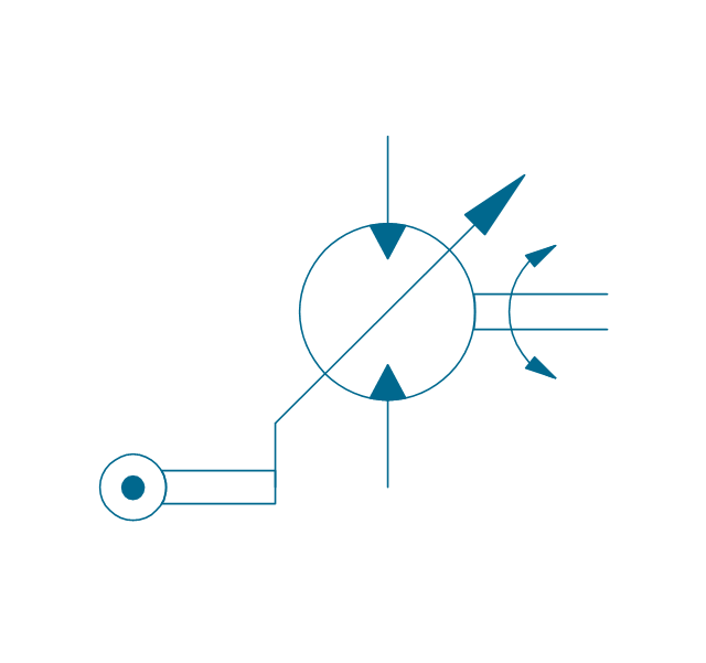
Pump, var., solenoid
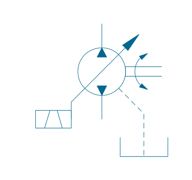
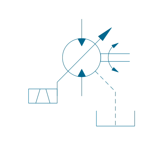
Pump, var., solenoid, drain

Pump, var., solenoid 2

Pump, var., solenoid 2, drain
Pump, var., var. solenoid
Pump, var., var. solenoid, drain
Pump, var., var. solenoid 2
Pump, var., var. solenoid 2, drain

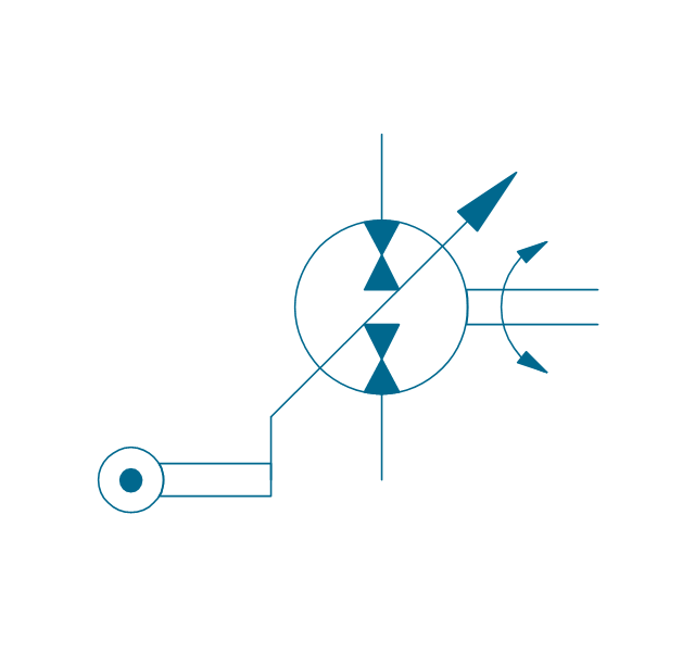
Pump, var., var., roller
Pump, var., roller, drain
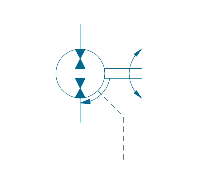
Motor, fixed, external drain
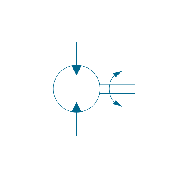
Motor, fixed, external drain
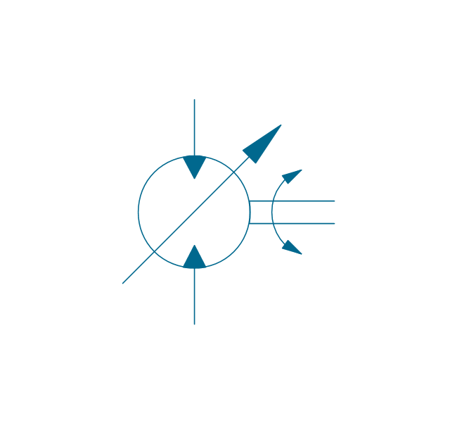
Motor, variable
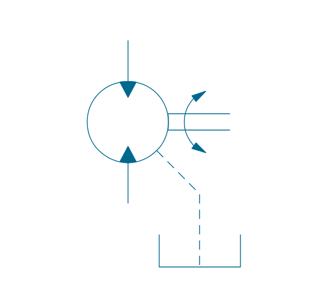
Motor, variable, external drain
Motor, var., manual override
Motor, var., manual override, drain

Motor, var., solenoid

Motor, var., solenoid, drain

Motor, var., solenoid 2
Motor, var., solenoid 2, drain
Motor, var., var. solenoid
Motor, var., var. solenoid, drain

Motor, var., var. solenoid 2
Motor, var., var. solenoid 2, drain
Motor, var., var., roller
Motor, var., roller, drain
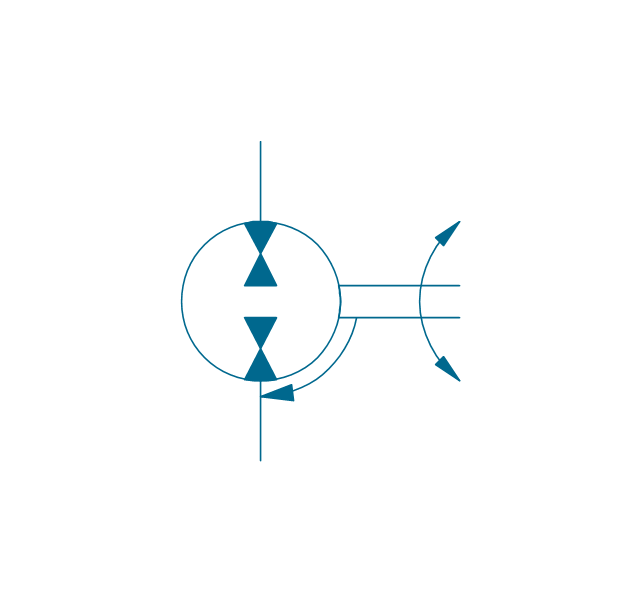
Pump-motor, fixed, external drain
Pump-motor, fixed, external drain
Pump-motor, variable
Pump-motor, variable, external drain
Pump-motor, var., manual override
Pump-motor, var., manual override, drain
Pump-motor, var., solenoid

Pump-motor, var., solenoid, drain

Pump-motor, var., solenoid 2
Pump-motor, var., solenoid 2, drain
Pump-motor, var., var. solenoid
Pump-motor, var., var. solenoid, drain

Pump-motor, var., var. solenoid 2

Pump-motor, var., var. solenoid 2, drain
Pump-motor, var., var., roller
Pump-motor, var., roller, drain
Pump, fixed 2
Pump, fixed 2, drain
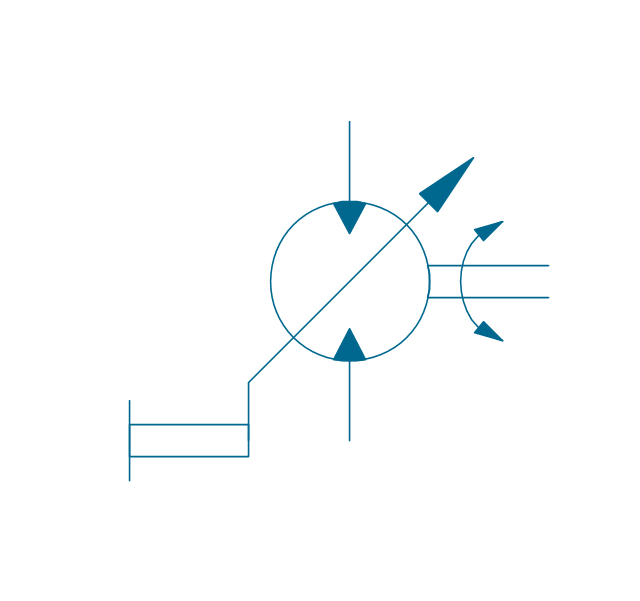
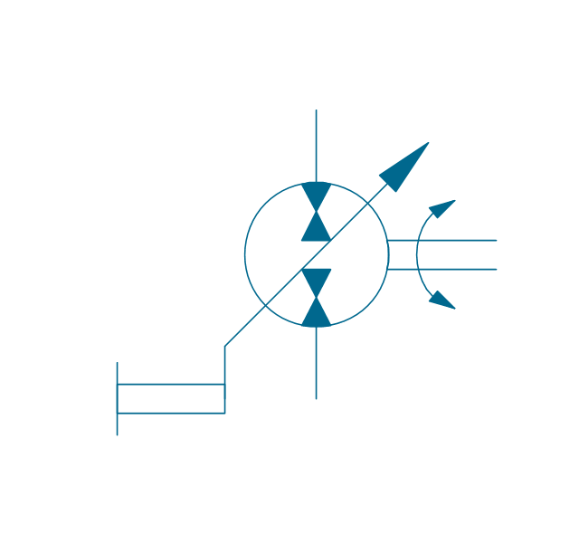
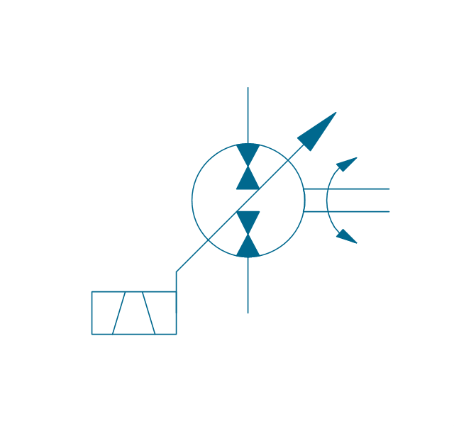
Pump, variable (sgl side)
-hydraulic-pumps-and-motors---vector-stencils-library.png--diagram-flowchart-example.png)
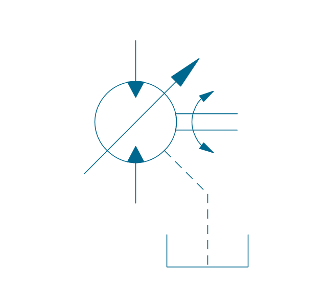
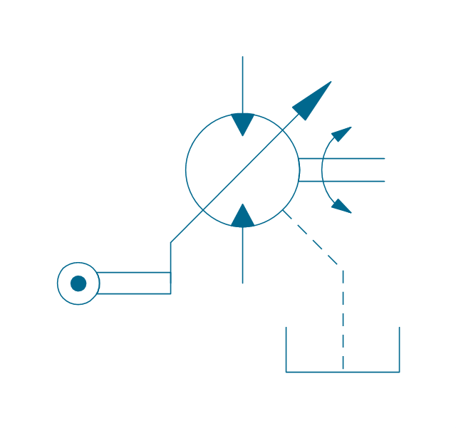
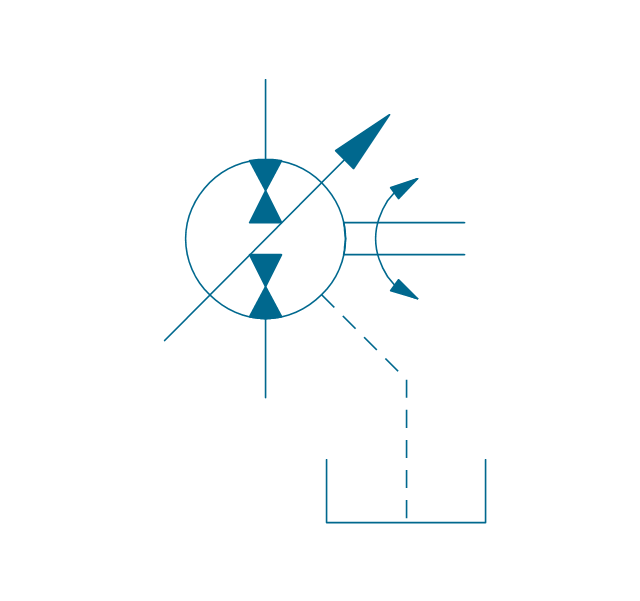
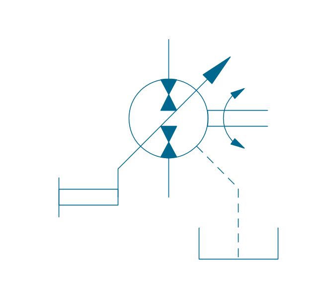
Pump, variable (sgl side), drain
,-drain-hydraulic-pumps-and-motors---vector-stencils-library.png--diagram-flowchart-example.png)
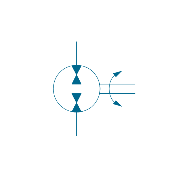
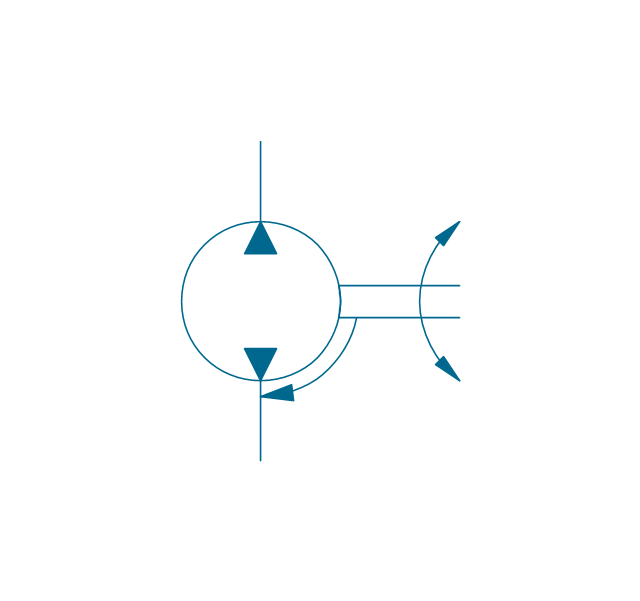
Pump, variable (dbl side)
-hydraulic-pumps-and-motors---vector-stencils-library.png--diagram-flowchart-example.png)
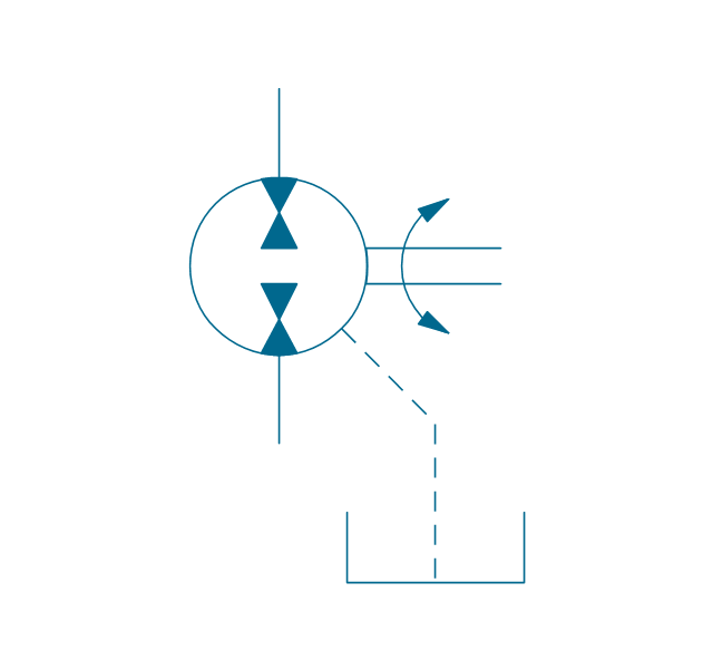
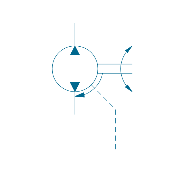
Pump, variable (dbl side), drain
,-drain-hydraulic-pumps-and-motors---vector-stencils-library.png--diagram-flowchart-example.png)
Motor, fixed 2
Motor, variable (sgl side)
-hydraulic-pumps-and-motors---vector-stencils-library.png--diagram-flowchart-example.png)
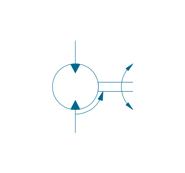
Motor, variable (dbl side)
-hydraulic-pumps-and-motors---vector-stencils-library.png--diagram-flowchart-example.png)
Motor, fixed 2, drain
Motor, variable (sgl side), drain
,-drain-hydraulic-pumps-and-motors---vector-stencils-library.png--diagram-flowchart-example.png)
Motor, variable (dbl side), drain
,-drain-hydraulic-pumps-and-motors---vector-stencils-library.png--diagram-flowchart-example.png)
Pump-motor, fixed 2
Pump-motor, fixed 2, drain
Pump-motor, variable (sgl side)
-hydraulic-pumps-and-motors---vector-stencils-library.png--diagram-flowchart-example.png)
Pump-motor, variable (sgl side), drain
,-drain-hydraulic-pumps-and-motors---vector-stencils-library.png--diagram-flowchart-example.png)
Pump-motor, variable (dbl side)
-hydraulic-pumps-and-motors---vector-stencils-library.png--diagram-flowchart-example.png)
Pump-motor, variable (dbl side), drain
,-drain-hydraulic-pumps-and-motors---vector-stencils-library.png--diagram-flowchart-example.png)
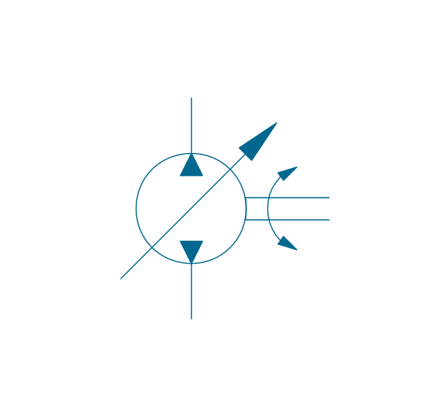
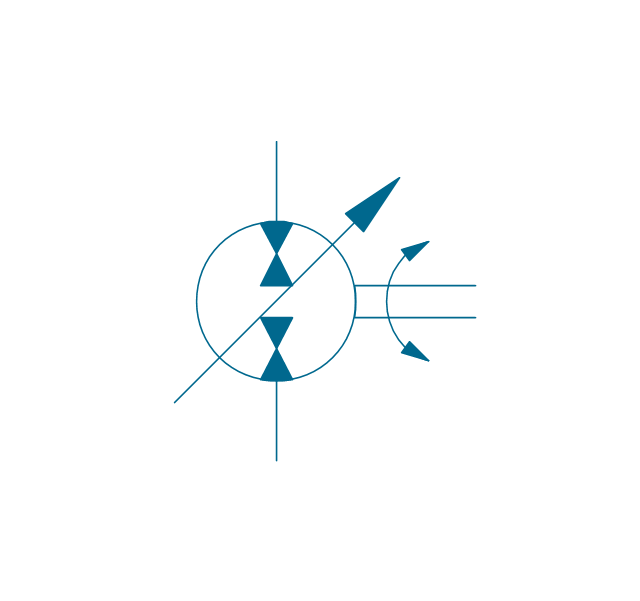
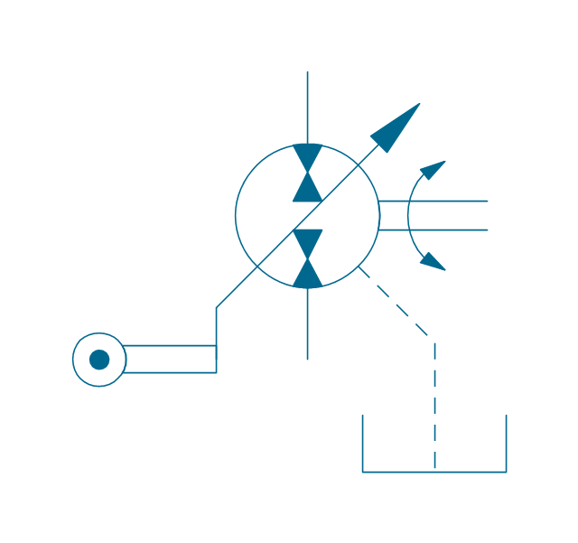
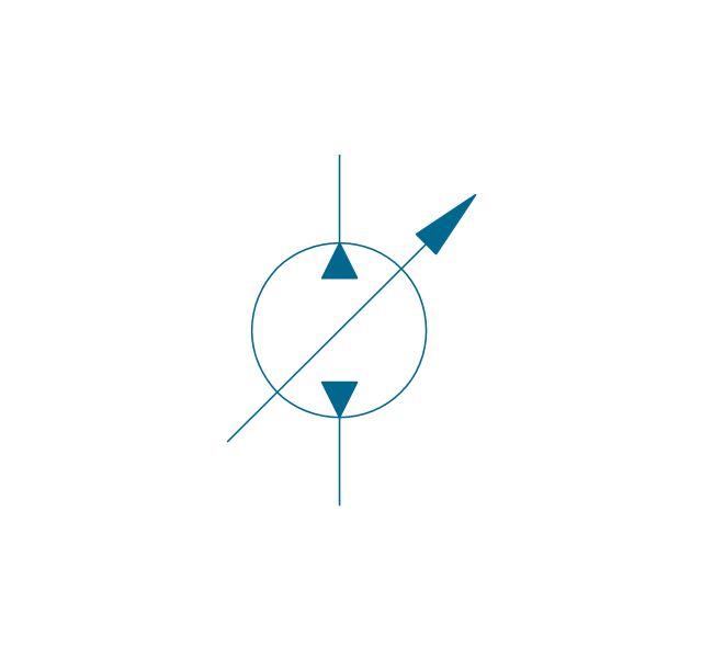
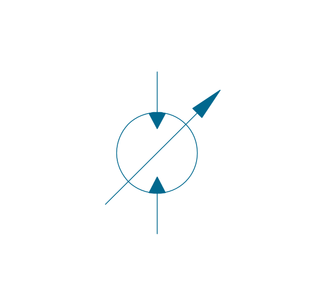
Pump, variable displacement
Motor, variable displacement
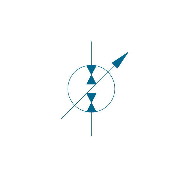
Pump-motor, variable displacement
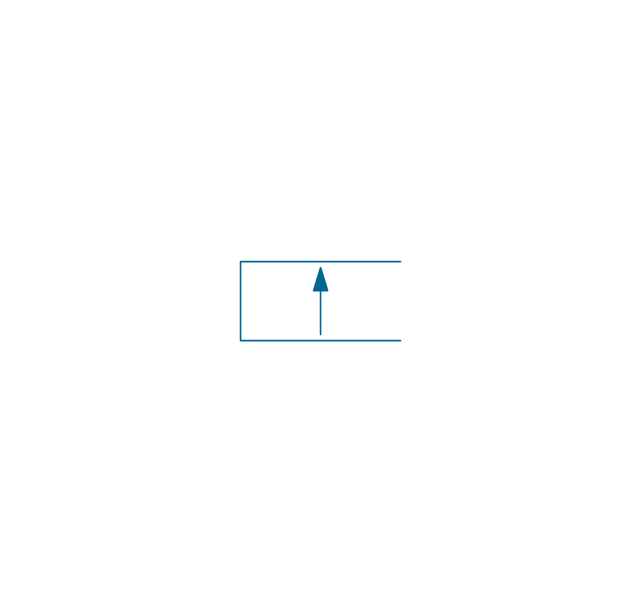
Floating motor
Pressure compensator
The vector stencils library "Pumps" contains 82 symbols of pumps, compressors, fans, turbines, and power generators.
Use these icons to design pumping systems, air and fluid compression systems, and industrial process diagrams.
"A pump is a device that moves fluids (liquids or gases), or sometimes slurries, by mechanical action. Pumps can be classified into three major groups according to the method they use to move the fluid: direct lift, displacement, and gravity pumps.
Pumps operate by some mechanism (typically reciprocating or rotary), and consume energy to perform mechanical work by moving the fluid. Pumps operate via many energy sources, including manual operation, electricity, engines, or wind power, come in many sizes, from microscopic for use in medical applications to large industrial pumps.
Mechanical pumps serve in a wide range of applications such as pumping water from wells, aquarium filtering, pond filtering and aeration, in the car industry for water-cooling and fuel injection, in the energy industry for pumping oil and natural gas or for operating cooling towers. In the medical industry, pumps are used for biochemical processes in developing and manufacturing medicine, and as artificial replacements for body parts, in particular the artificial heart and penile prosthesis.
In biology, many different types of chemical and bio-mechanical pumps have evolved, and biomimicry is sometimes used in developing new types of mechanical pumps." [Pump. Wikipedia]
The example "Design elements - Pumps" was created using the ConceptDraw PRO diagramming and vector drawing software extended with the Chemical and Process Engineering solution from the Engineering area of ConceptDraw Solution Park.
Pump symbols

Mechanical Design Software

Technical Drawing Software

Process Flow Diagram Symbols

"A hydraulic circuit is a system comprising an interconnected set of discrete components that transport liquid. The purpose of this system may be to control where fluid flows (as in a network of tubes of coolant in a thermodynamic system) or to control fluid pressure (as in hydraulic amplifiers).
... hydraulic circuit theory works best when the elements (passive component such as pipes or transmission lines or active components such as power packs or pumps) are discrete and linear. This usually means that hydraulic circuit analysis works best for long, thin tubes with discrete pumps, as found in chemical process flow systems or microscale devices." [Hydraulic circuit. Wikipedia]
The engineering drawing example "Hydraulic circuits" was redrawn using ConceptDraw PRO diagramming and vector drawing software from the Wikimedia Commons file: Hydraulic circuits.png.
[commons.wikimedia.org/ wiki/ File:Hydraulic_ circuits.png]
This file is licensed under the Creative Commons Attribution-Share Alike 3.0 Unported license.
[creativecommons.org/ licenses/ by-sa/ 3.0/ deed.en]
The engineering drawing example "Hydraulic circuits" is included in the Mechanical Engineering solution from the Engineering area of ConceptDraw Solution Park.
Hydraulic circuit schematic

Technical Drawing Software

 Chemical and Process Engineering
This chemical engineering solution extends ConceptDraw DIAGRAM.9.5 (or later) with process flow diagram symbols, samples, process diagrams templates and libraries of design elements for creating process and instrumentation diagrams, block flow diagrams (BFD
The vector stencils library "Pumps" contains 82 symbols of pumps, compressors, fans, turbines, and power generators.
Use these icons to design pumping systems, air and fluid compression systems, and industrial process diagrams in the ConceptDraw PRO software extended with the Chemical and Process Engineering solution from the Chemical and Process Engineering area of ConceptDraw Solution Park.
www.conceptdraw.com/ solution-park/ engineering-chemical-process
In-line pump

In-line pump 2

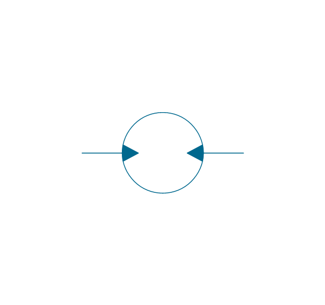
Positive displacement

Centrifugal pump (arrows)
-pumps---vector-stencils-library.png--diagram-flowchart-example.png)
Centrifugal pump

Rotary pump 1

Rotary pump 2

Proportioning pump

Pump vacuum

Pump positive displacement

Pump piston

Pump liquid ring

Pump oil-sealed rotary (single)
-pumps---vector-stencils-library.png--diagram-flowchart-example.png)
Pump oil-sealed rotary (multi)
-pumps---vector-stencils-library.png--diagram-flowchart-example.png)
Pump roots

Pump gas ballast

Pump turbo molecular

Pump general

Pump centrifugal

Pump positive displacement 2

Pump gear

Pump screw

Pump helical rotor

Pump reciprocating

Pump diaphragm

Pump liquid jet

Pump centrifugal 2

Pump diaphragm 2

Pump gear 2

Pump general 2

Pump helical rotor 2

Pump reciprocating 2

Pump screw 2

Compressor general

Compressor container

Compressor rotary

Compressor screw

Compressor reciprocating

Compressor ejector

Compressor general 2

Compressor liquid ring

Compressor positive displacement

Compressor reciprocating 2

Compressor reciprocating diaphragm

Compressor roller vane

Compressor rotary 2

Compressor screw 2

Compressor turbo

Compressor general 3

Compressor reciprocating 3

Compressor reciprocating diaphragm 2

Compressor roller vane 2

Compressor rotary 3

Compressor screw 3

Rotary compressor

Motor driven turbine

Compressor (center line)
-pumps---vector-stencils-library.png--diagram-flowchart-example.png)
Compressor

Turbine

Turbine (center line)
-pumps---vector-stencils-library.png--diagram-flowchart-example.png)
Reciprocating pump/compressor

Reciprocating pump 2

Fan general

Fan radial

Fan axial

Fan general 2

Fan radial 2

Fan axial 2

Centrifugal fan 2 (center circle)
-pumps---vector-stencils-library.png--diagram-flowchart-example.png)
Centrifugal fan

Axial flow fan supply

Axial flow fan exhaust

Axial flow fan exhaust wall-type

Axial flow fan supply wall-type

Axial flow fan 2

Ejector / injector

Spray

Shower

Fan blades horizontal

Fan blades vertical

Fan blades (4)
-pumps---vector-stencils-library.png--diagram-flowchart-example.png)
Triple fan blades

The vector stencil library "HVAC equipment" contains 84 HVAC equipment symbols as pumps, fans, condensers, pipe coils, silencers, etc.
Use it for drawing HVAC system diagrams, heating, ventilation, air conditioning, refrigeration, automated building control, and environmental control design floor
plans and equipment layouts.
"HVAC (heating, ventilation, and air conditioning) is the technology of indoor and vehicular environmental comfort. HVAC system design is a subdiscipline of mechanical engineering, based on the principles of thermodynamics, fluid mechanics, and heat transfer. Refrigeration is sometimes added to the field's abbreviation as HVAC&R or HVACR, or ventilating is dropped as in HACR (such as the designation of HACR-rated circuit breakers).
HVAC is important in the design of medium to large industrial and office buildings such as skyscrapers and in marine environments such as aquariums, where safe and healthy building conditions are regulated with respect to temperature and humidity, using fresh air from outdoors." [HVAC. Wikipedia]
The vector stencils example "Design elements - HVAC equipment" is included in HVAC Plans solution from the Building Plans area of ConceptDraw Solution Park.
HVAC equipment symbols

- Mechanical Drawing Symbols | Mechanical Engineering ...
- Mechanical Drawing Symbols | Process Flow Diagram Symbols ...
- Mechanical Drawing Symbols | Mechanical Engineering ...
- Design elements - Hydraulic pumps and motors | Mechanical ...
- Mechanical Drawing Symbols | Mechanical Engineering ...
- Technical Drawing Software | Mechanical Engineering | Design ...
- Mechanical Engineering | Mechanical Drawing Symbols ...
- Mechanical Drawing Symbols | Mechanical Engineering ...
- Mechanical Engineering | Technical Drawing Software | Mechanical ...
- Design elements - Pneumatic pumps and motors | Mechanical ...
- ConceptDraw Solution Park | Mechanical Engineering | Design ...
- Mechanical Drawing Symbols | Mechanical Engineering | Technical ...
- Mechanical Drawing Symbols | Design elements - Hydraulic pumps ...
- Design elements - Hydraulic pumps and motors | Mechanical ...
- Mechanical Drawing Symbols | Technical Drawing Software ...
- Mechanical Drawing Symbols | Mechanical Engineering | Technical ...
- Technical Drawing Software | Mechanical Engineering | Mechanical ...
- Technical Drawing Software | Mechanical Engineering | Technical ...
- Mechanical Drawing Symbols | Mechanical Engineering | Electrical ...