UML Deployment Diagram. Design Elements

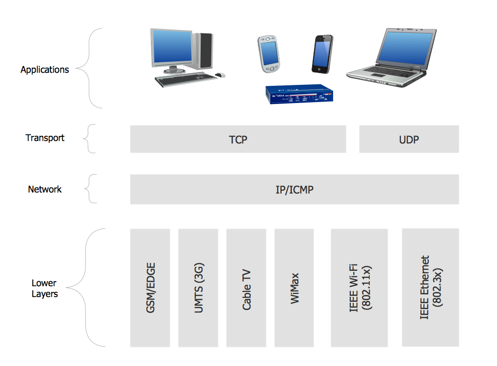
Personal area (PAN) networks. Computer and Network Examples
 networks")

Network Diagram Software

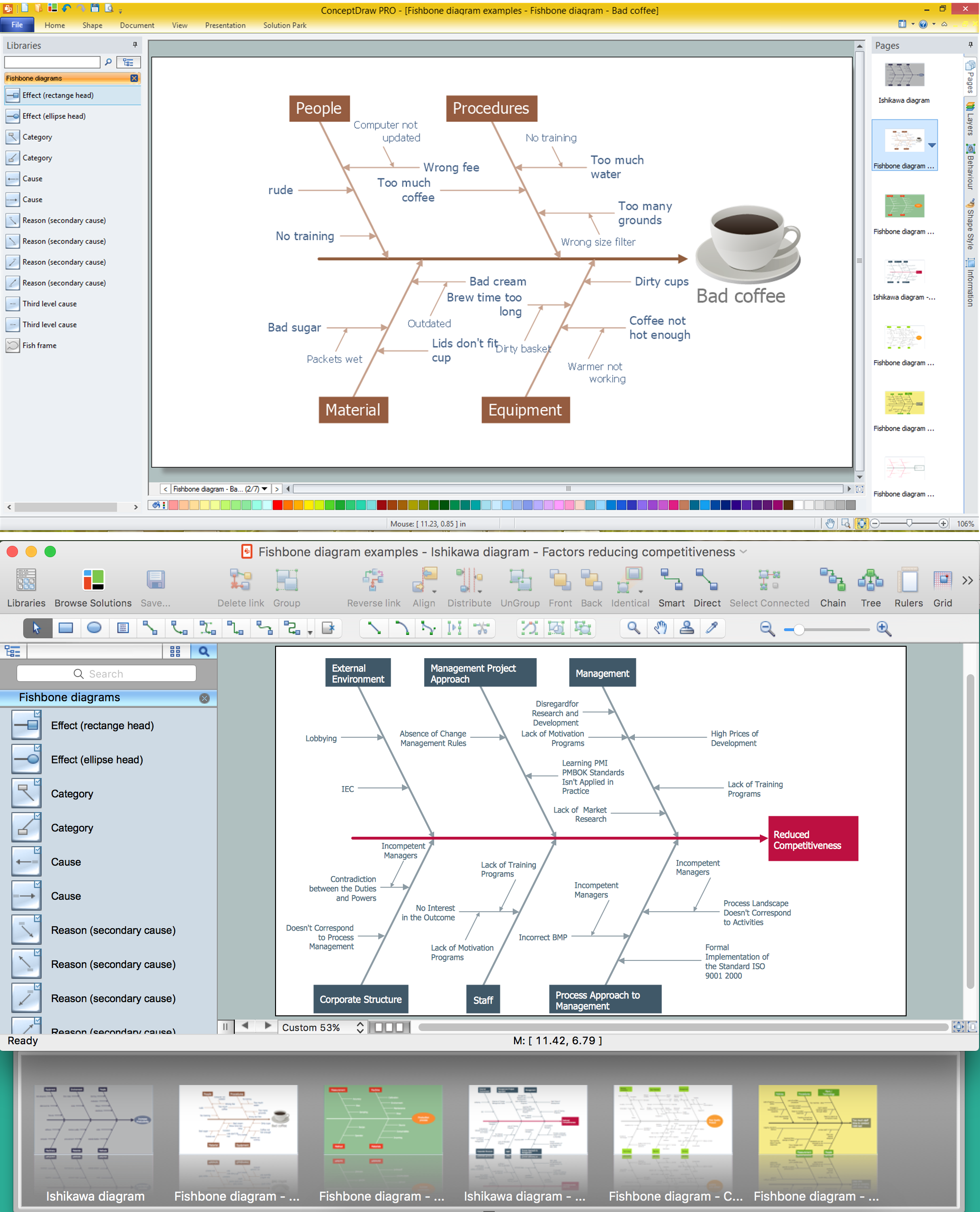
"Causes in the diagram are often categorized, such as to the 6 M's ...
The 6 Ms (used in manufacturing industry):
(1) Machine (technology);
(2) Method (process);
(3) Material (Includes Raw Material, Consumables and Information.);
(4) Man Power (physical work)/ Mind Power (brain work): Kaizens, Suggestions;
(5) Measurement (Inspection);
(6) Milieu/ Mother Nature (Environment).
The original 6Ms used by the Toyota Production System have been expanded by some to include the following and are referred to as the 8Ms. However, this is not globally recognized. It has been suggested to return to the roots of the tools and to keep the teaching simple while recognizing the original intent; most programs do not address the 8Ms.
(7) Management/ Money Power;
(8) Maintenance." [Ishikawa diagram. Wikipedia]
This 8Ms Ishikawa diagram (manufacturing cause and effect diagram) template is included in the Fishbone Diagram solution from the Management area of ConceptDraw Solution Park.
8Ms Ishikawa diagram

Examples of Flowcharts, Org Charts and More


Using Fishbone Diagrams for Problem Solving
Simple Diagramming

How Do Fishbone Diagrams Solve Manufacturing Problems

Fishbone Diagram Procedure

Venn Diagram Examples for Problem Solving
Fishbone Diagram Problem Solving

"A logic gate is an idealized or physical device implementing a Boolean function, that is, it performs a logical operation on one or more logical inputs, and produces a single logical output. Depending on the context, the term may refer to an ideal logic gate, one that has for instance zero rise time and unlimited fan-out, or it may refer to a non-ideal physical device...
Logic gates are primarily implemented using diodes or transistors acting as electronic switches, but can also be constructed using electromagnetic relays (relay logic), fluidic logic, pneumatic logic, optics, molecules, or even mechanical elements. With amplification, logic gates can be cascaded in the same way that Boolean functions can be composed, allowing the construction of a physical model of all of Boolean logic, and therefore, all of the algorithms and mathematics that can be described with Boolean logic.
Logic circuits include such devices as multiplexers, registers, arithmetic logic units (ALUs), and computer memory, all the way up through complete microprocessors, which may contain more than 100 million gates. In practice, the gates are made from field-effect transistors (FETs), particularly MOSFETs (metal–oxide–semiconductor field-effect transistors).
Compound logic gates AND-OR-Invert (AOI) and OR-AND-Invert (OAI) are often employed in circuit design because their construction using MOSFETs is simpler and more efficient than the sum of the individual gates.
In reversible logic, Toffoli gates are used." [Logic gate. Wikipedia]
The logic gate diagram template for the ConceptDraw PRO diagramming and vector drawing software is included in the Electrical Engineering solution from the Engineering area of ConceptDraw Solution Park.
Logic gate diagram

 Fishbone Diagram
Fishbone Diagrams solution extends ConceptDraw DIAGRAM software with templates, samples and library of vector stencils for drawing the Ishikawa diagrams for cause and effect analysis.
Ishikawa Diagram
- How Do Fishbone Diagrams Solve Manufacturing Problems ...
- Fishbone Diagrams | Fishbone Diagram Example | Fishbone ...
- Data Flow Diagram Model | Process Flowchart | Bar Diagrams for ...
- Logical network topology diagram | Local area network (LAN ...
- Cause and effect diagram - Increase in productivity | Home area ...
- Fully Connected Network Topology Diagram | Network Topologies ...
- Network Diagram Software LAN Network Diagrams & Diagrams for ...
- Total Quality Management Value | 4 Ms fishbone diagram ...
- Draw The Diagram Showing Lan To Wan Connection And Explain
- Draw Fishbone Diagram on MAC Software | Network wiring cable ...
- Simple Drawing Applications for Mac | Draw Fishbone Diagram on ...
- Successful Strategic Plan | Process Flowchart | Physical Security ...
- Free Sentence Diagrammer | Draw Fishbone Diagram on MAC ...
- Cause And Effect Diagram Manufacturing
- Illustrate A Digital Office With A Layout Diagram
- Network Diagram Software LAN Network Diagrams & Diagrams for
- Network Diagram Software Backbone Network | Network Diagram ...
- Free-body diagram | Physics Diagrams | How to Draw Physics ...
- ER diagram tool for OS X | Create Flow Chart on Mac | Network ...
- Fishbone Diagram Design Element | Metropolitan area networks ...