Network Diagram Software Backbone Network


HelpDesk
How to Draw a Fishbone Diagram with ConceptDraw PRO

Network Printer

Draw Network Diagram based on Templates and Examples

Design Element: Network Layout for Network Diagrams
.png "Network Diagramming Tools, Design Elements - Network Layout (Win Mac)")
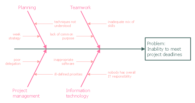
This example was created on the base of the figure from the website of the Iowa State University Center for Excellence in Learning and Teaching.
"Fishbone.
What: The fishbone technique uses a visual organizer to identify the possible causes of a problem.
Benefits: This technique discourages partial or premature solutions and demonstrates the relative importance of, and interactions between, different parts of a problem.
How: On a broad sheet of paper, draw a long arrow horizontally across the middle of the page pointing to the right. Label the arrowhead with the title of the issue to be explained. This is the "backbone" of the "fish." Draw "spurs" from this "backbone" at about 45 degrees, one for every likely cause of the problem that the group can think of; and label each. Sub-spurs can represent subsidiary causes. The group considers each spur/ sub-spur, taking the simplest first, partly for clarity but also because a simple explanation may make more complex ones unnecessary. Ideally, the fishbone is redrawn so that position along the backbone reflects the relative importance of the different parts of the problem, with the most important at the head." [celt.iastate.edu/ creativity/ techniques.html]
The fishbone diagram example "Inability to meet project deadlines" was created using the ConceptDraw PRO diagramming and vector drawing software extended with the Fishbone Diagrams solution from the Management area of ConceptDraw Solution Park.
Ishikawa diagram
 AWS Architecture Diagrams
AWS Architecture Diagrams with powerful drawing tools and numerous predesigned Amazon icons and AWS simple icons is the best for creation the AWS Architecture Diagrams, describing the use of Amazon Web Services or Amazon Cloud Services, their application for development and implementation the systems running on the AWS infrastructure. The multifarious samples give you the good understanding of AWS platform, its structure, services, resources and features, wide opportunities, advantages and benefits from their use; solution’s templates are essential and helpful when designing, description and implementing the AWS infrastructure based systems. Use them in technical documentation, advertising and marketing materials, in specifications, presentation slides, whitepapers, datasheets, posters, etc.
- Network Diagram Software Backbone Network | Network Diagram ...
- Network Diagram Software Backbone Network | Network Topologies ...
- Drow Diagram For Backbone Network Describe In Detail
- Network Diagram Software Backbone Network | Network Diagram ...
- Network Diagram Software Backbone Network | Cisco Network ...
- With The Help Of A Diagram Describe The Backbone Network
- Network Diagram Software Backbone Network | Hotel Network ...
- Backbone Network Architecture Diagram
- Network Printer | Network Diagram Software Backbone Network ...
- Network Diagram Software Backbone Network | Process Flowchart ...
- Network Diagram Software Backbone Network | Fishbone Diagram ...
- Network Diagram Software Backbone Network | How to Draw a ...
- How to Draw a Computer Network Diagrams | Network Diagram ...
- Telecommunication Network Diagrams | Network Diagram Software ...
- Network Diagram Software Backbone Network | Computer Network ...
- Network Diagram Software Backbone Network | Metropolitan area ...
- Network Diagram Software Backbone Network | Create Flow Chart ...
- 3D Network Diagram Software
- CCTV Network Diagram Software | Network Protocols | Network ...
- Backbone Transmission Network With Diagram