Personal area (PAN) networks. Computer and Network Examples
 networks")

Diagram of a Basic Computer Network. Computer Network Diagram Example

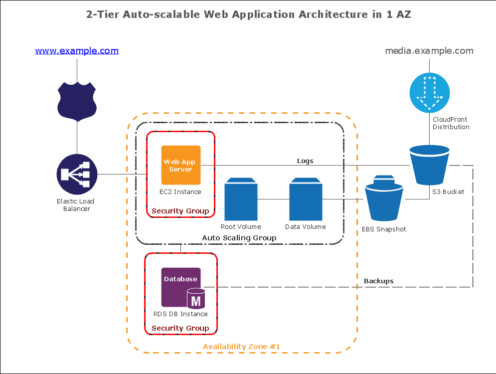
How To create Diagrams for Amazon Web Services architecture
How to Dramatically Reduce Drawing Time - New connection modes
Fishbone Diagram Problem Solving

Hybrid Network Topology

ConceptDraw DIAGRAM : Able to Leap Tall Buildings in a Single Bound
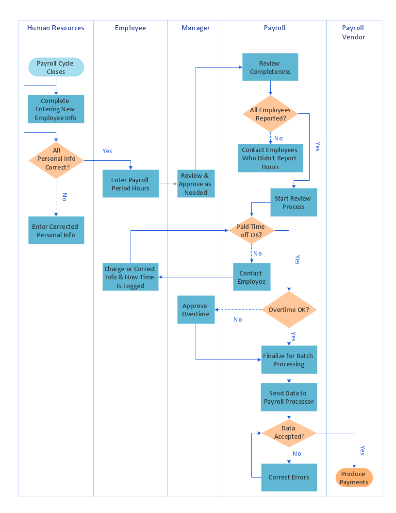
 Business Process Mapping
The Business Process Mapping solution for ConceptDraw DIAGRAM is for users involved in process mapping and creating SIPOC diagrams.
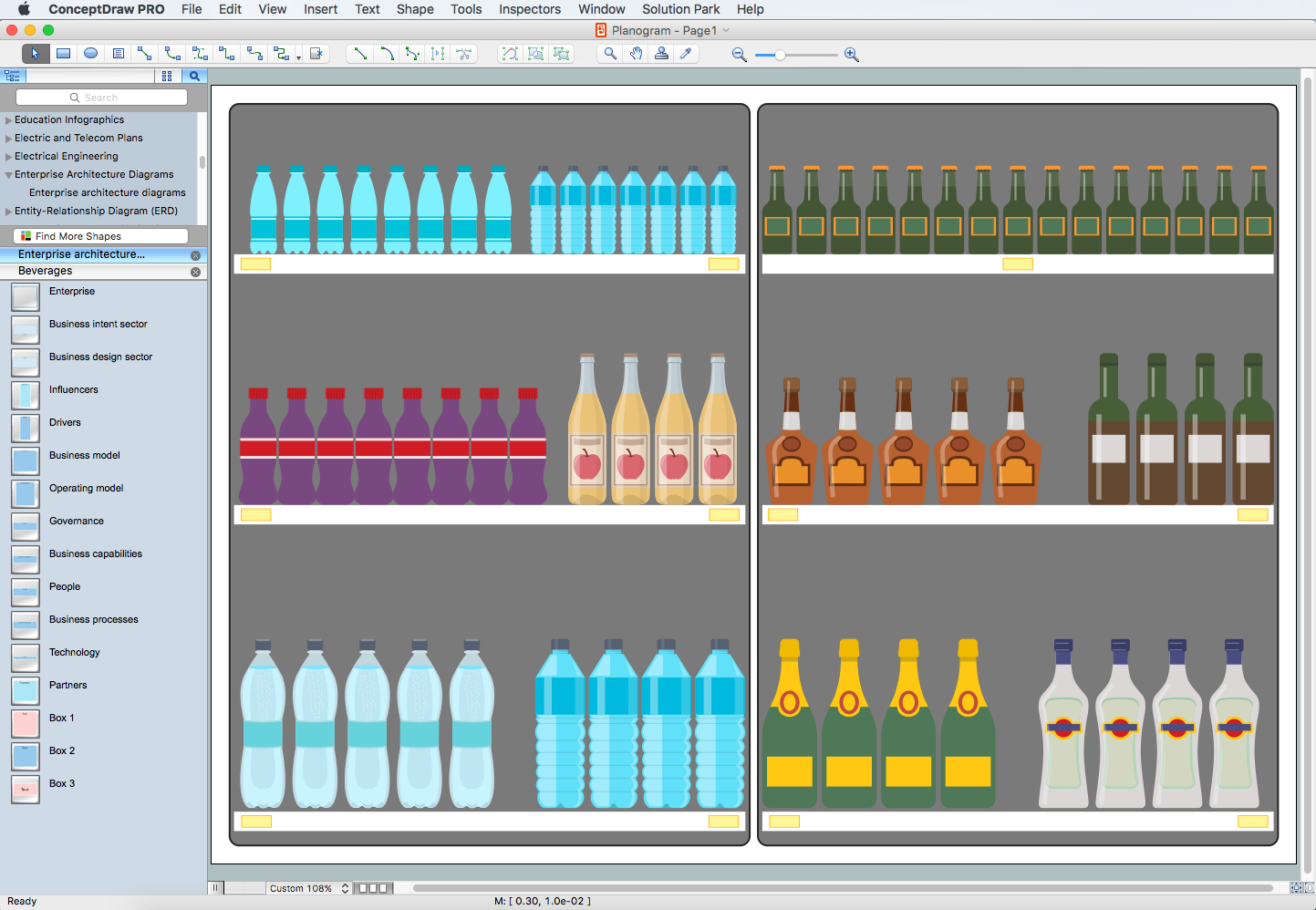
Planogram Software and Retail Plan Software
Campus Area Networks (CAN). Computer and Network Examples

- Diagram For Pan Nerwork
- Business Process Mapping | Head Pan Diagram And Uses
- Local area network (LAN). Computer and Network Examples ...
- UML Class Diagram Constructor | Process Flowchart | Personal area ...
- What Are The Uses Of Headpan
- Draw A Headpan
- What Is Headpan Used For
- Well Label Diagram Of Head Pan
- Local area network (LAN). Computer and Network Examples ...
- Personal area ( PAN ) networks. Computer and Network Examples ...