How To use House Electrical Plan Software


Piping and Instrumentation Diagram Software

Mechanical Drawing Symbols

Half Pipe Plans
ConceptDraw Arrows10 Technology
Process Flow Chart

IDEF9 Standard

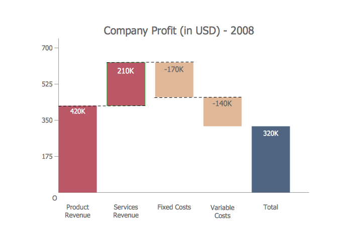
Waterfall Bar Chart
Cisco Network Design. Cisco icons, shapes, stencils, symbols and design elements

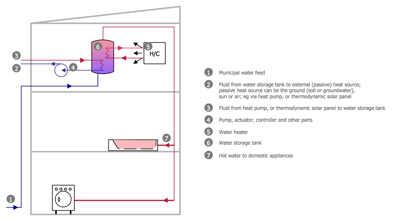
The vector stencils library "HVAC control equipment" contains 48 HVAC symbols. Use it for drawing HVAC systems diagrams, heating, ventilation, air conditioning, refrigeration, automated building control, and environmental control design building plans and equipment layouts. The symbols example "HVAC control equipment - Vector stencils library" was created using the ConceptDraw PRO diagramming and vector drawing software extended with the HVAC Plans solution from the Building Plans area of ConceptDraw Solution Park.
Duct, sgl line

Duct, dbl line

Return duct, sgl line

Return duct, dbl line

Supply duct, sgl line

Supply duct, dbl line

Return duct 2, sgl line

Return duct 2, dbl line

Supply duct extension, sgl line

Supply duct extension, dbl line

Return duct extension, sgl line

Return duct extension, dbl line

2-fan section, sgl line

2-fan section, dbl line

3-fan section, sgl line

3-fan section, dbl line

4-fan section, sgl line

4-fan section, dbl line

VAV box

DD-VAV box

Fan coil housing

Unit heater

Centrifugal fan

Propeller fan

Vane axial fan

Damper

Filter

Air flow station

Humidifier

Htg/clg coil

Valve

Water flow meter

Pump


Cooling tower

Converter

Heat exchanger

Boiler

Equipment

Starter

VSD

Side to bottom pipe

Side to bottom pipe, arrow
Side to side pipe

Side to side pipe, arrow
Top to bottom pipe

Top to bottom pipe, arrow
Pipe flow arrow
- Office Layout Plans | Sample Key Plan Drawing
- Two Way Switch Symbol On Floor Plan
- Refrigerator Symbol Floor Plan
- How to Create a Residential Plumbing Plan | Plumbing and Piping ...
- Security system floor plan | Plumbing and Piping Plans | Design ...
- Toilet Symbol Floor Plan
- Design elements - Lighting | Plumbing and Piping Plans | How to ...
- Exhaust Fan Floor Plan Symbol
- Plumbing and Piping Plans | How to Create a Residential Plumbing ...
- Building Drawing . Design Element: Piping Plan | Process Flow ...