Process Flow Diagram Symbols
Piping and Instrumentation Diagram Software

Mechanical Drawing Symbols

Electrical Symbols, Electrical Diagram Symbols

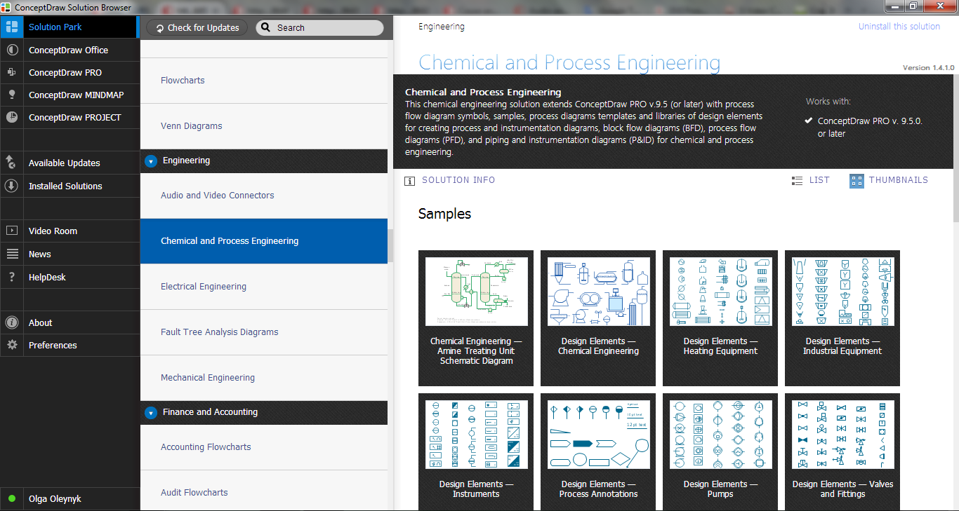
 Chemical and Process Engineering
This chemical engineering solution extends ConceptDraw DIAGRAM.9.5 (or later) with process flow diagram symbols, samples, process diagrams templates and libraries of design elements for creating process and instrumentation diagrams, block flow diagrams (BFD
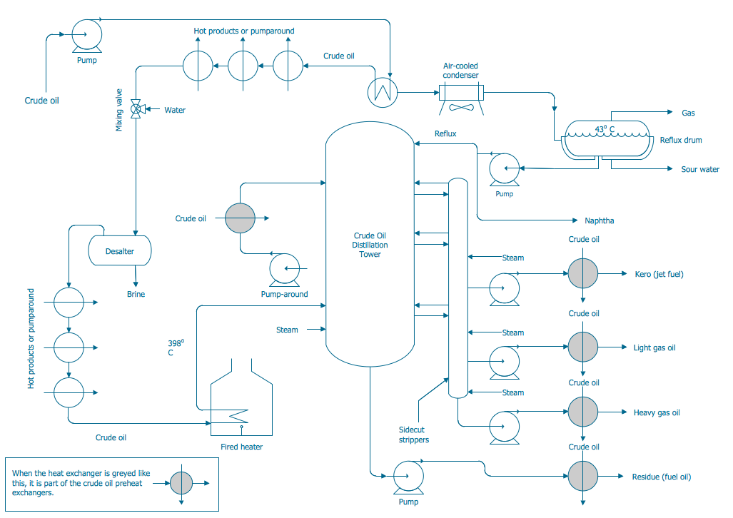
Process and Instrumentation Diagram
Flow chart Example. Warehouse Flowchart


Electrical Symbols — Stations

Electrical Symbols — Analog and Digital Logic

Technical Drawing Software

- Industrial Instrument Symbol In Pdf
- Piping And Instrumentation Diagram Symbols Pdf
- Industrial Valve Symbols Pdf
- Plumbing and Piping Plans | Pipe Drawing Symbols Pdf
- Plumbing and Piping Plans | Piping Valve Symbols Chart Pdf
- Pipe Fitting Valves Symbol Pdf
- Piping Valve Drawing Symbols Pdf
- Plumbing Symbols Pdf
- Plumbing and Piping Plans | Pipe Fitting Symbols Pdf Free
- Plumbing and Piping Plans | Isometric Piping Drawing Symbols Pdf