HelpDesk
How to Create a Telecommunication Network Diagram
Telecommunication network diagram displays components and connections in a telecommunication network: how they are interacted between each other and with end-users. Telecommunication network diagrams usually created by system engineers for planning telecom networks. Also, they may be useful for network management. Telecom network diagram visualizes the level of security and user access to certain equipment and data within a current network. Telecom network diagram can be used to identify weak points of an entire network or a part of it. ConceptDraw DIAGRAM allows you to draw a simple and clear Telecommunication Network diagrams.HelpDesk
How to Create Cisco Network Diagram
Cisco Network chart can be a great start for detailed network documentation, as well as serve as a visual instruction for new IT staff, or as a detailed illustration for a presentation. The easiest way to design the Cisco Network diagram using standard Cisco product symbols is using ConceptDraw DIAGRAM powered by the Cisco Network Diagrams solution. The Cisco Network Diagrams solution uses Cisco network symbols and icons to visually document the Cisco network topology and design of Cisco network diagrams. Using ConceptDraw libraries you can access a wide array of Cisco network icons, so you can quickly prototype a new network or document an existing one.HelpDesk
How to Create Cisco Network Diagram
The easiest way to design Cisco Network diagram using standard Cisco product symbols is using ConceptDraw DIAGRAM powered by Cisco Network Diagrams solution. The Cisco Network Diagrams solution uses Cisco network symbols to visually document the topology and design of Cisco networks.HelpDesk
How to Make Network Diagram
ConceptDraw DIAGRAM allows you to represent and communicate network architecture, topology, and design to engineers, stakeholders, and end-users.HelpDesk
How to Create a Wireless Network Diagram Using ConceptDraw Solutions
A wireless network diagram is a specialized type of computer network diagrams. Wireless Network diagrams are used to develop, operate and maintain the WLAN systems. Making a Wireless Network diagram involves many different elements that can be managed using ConceptDraw DIAGRAM. With ConceptDraw DIAGRAM you can easily create and communicate the Wireless Network diagram of any complexity.Using Remote Networking Diagrams
Remote Networking - We explain the method most people use to connect to the Internet.ConceptDraw DIAGRAM Network Diagram Tool
With ConceptDraw DIAGRAM you can diagram a network or create a computer network diagram using specialized libraries of network components such as computers, hubs, smart connectors etc. that simulate network design topologies and devices, network architectures (all these shapes are parts of network diagram tool ConceptDraw DIAGRAM).Network Diagramming with ConceptDraw DIAGRAM
Draw detailed Computer Network Diagrams, Designs, Schematics, and Network Maps with ConceptDraw DIAGRAM in no time! Pre-drawn shapes representing computers, network devices plus smart connectors help create accurate diagrams and documentation.HelpDesk
How to Create a CCTV Diagram
CCTV (Closed-circuit television) diagram is used to depict a system of video monitoring. The CCTV diagram provides video cameras placement strategy.CCTV diagram should include the scheme of strategic placement of video cameras, which capture and transmit videos to either a private network of monitors for real-time viewing or to a video recorder for later reference. CCTV is commonly used for surveillance and security purposes. Using ConceptDraw DIAGRAM with the Security and Access Plans Solution lets you create professional looking video surveillance CCTV system plans, security plans, and access schemes.
Computer Network Diagrams
Computer Network Diagrams solution extends ConceptDraw DIAGRAM software with samples, templates and libraries of vector icons and objects of computer network devices and network components to help you create professional-looking Computer Network Diagrams, to plan simple home networks and complex computer network configurations for large buildings, to represent their schemes in a comprehensible graphical view, to document computer networks configurations, to depict the interactions between network's components, the used protocols and topologies, to represent physical and logical network structures, to compare visually different topologies and to depict their combinations, to represent in details the network structure with help of schemes, to study and analyze the network configurations, to communicate effectively to engineers, stakeholders and end-users, to track network working and troubleshoot, if necessary.
HelpDesk
How to Create a Hook-Up Diagram
Hook-up diagram of the audio-video system is a detailed drawing showing the audio video connections in a correct manner so that the system operates properly. Using the hook-up diagram you can understand how the elements of your audio-video system should be installed. ConceptDraw DIAGRAM allows you to draw the Hook Up diagram of Audio-Video system easily using the set of special libraries provided by Audio and Video Connectors solution.HelpDesk
How to Make a UML Diagram
The Unified Modeling Language™(UML) is a standard visual modeling language to document business processes and software architecture. UML uses several types of diagrams including Use Case Diagrams, Class, Package, Component, Composite Structure Diagrams, Deployments, Activities, and Interactions. The accepted standard used when modeling a system is known as the Unified Modeling Language (UML), a generic set of notations that are used when creating UML diagrams. These notations can visually represent requirements, subsystems, logical and physical elements, and structural and behavioral patterns, that are especially relevant to systems built using an object-oriented style.Using UML during the modeling process has a number of benefits — for one, the entire development team can share information and collaborate using a common language, diagrams, and software, something that's not possible when using a more task-specific programming language.
HelpDesk
How to Draw a Circular Arrows Diagram
The cyclic recurrence is a fundamental property of multiple systems. The cycle is a process which consists of elements (phases, stages, stages) following each other. Many processes in astronomy, biology, chemistry, physics, mathematics, etc. have a cycle properties. It is also widely used in information technologies and marketing analysis. Graphical representation of cyclic processes can have many forms. It can be a circle, parabola, hyperbola, ellipse, and others. A Circular Arrows Diagram is used as one of the statistical charts in the business, mass media and marketing. ConceptDraw DIAGRAM provides tools for making easy drawing Circular Arrows Diagrams.HelpDesk
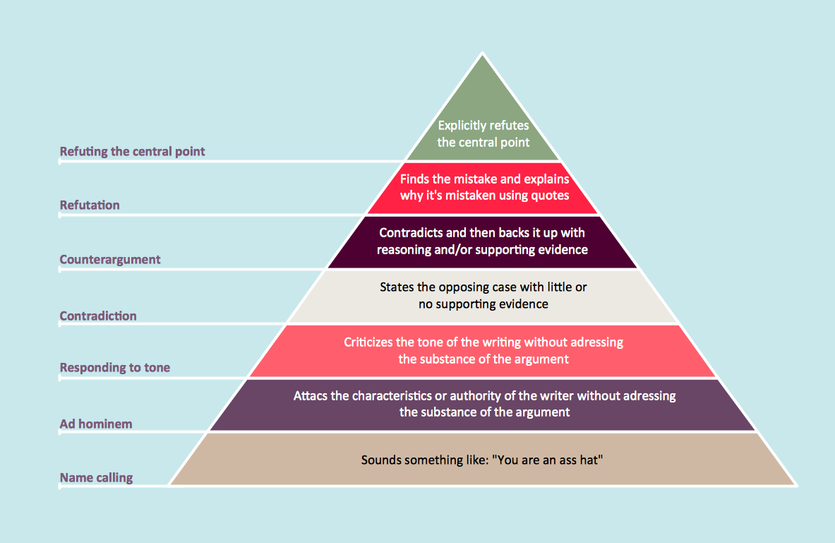
How to Draw a Pyramid Diagram
Pyramid diagram (triangle diagram) is used to represent data, which have hierarchy and basics. Due to the triangular form of a diagram, each pyramid section has a different width. The width of the segment shows the level of its hierarchy. Typically, the top of the pyramid is the data that are more important than the base data. A pyramid scheme can be used to show proportional and hierarchical relationships between some logically related items, such as departments within an organization, or successive elements of any process. This type of diagram is often used in marketing to display hierarchically related data, but it can be used in a variety of situations. ConceptDraw DIAGRAM allows you to make a pyramid diagram, quickly and easily using special libraries.HelpDesk
How to Create a Rack Diagram
A Rack Diagram represents the rack mounting of network and computer equipment that is installed as a server. Rack diagrams are used by system administrators and network architectors when making a decision regarding the purchase of network equipment. It is used to show how a particular server configuration can be composed, without making its physical installation. ConceptDraw DIAGRAM enhanced with the Rack Diagrams Solution can be successfully used for making various rack diagrams. It's important that the solution used to create a rack diagram contains templates that stick to industry standards, and supplies a big selection of device icons to cover multiple types of equipment for a number of network configurations.HelpDesk
How To Create an Affinity Diagram Using Solutions
The affinity diagram is designed to prepare the data for further analysis of the cause-effect relationships. The Affinity diagram shows the structure of large, complex factors that have an influence on a problem, and then divides them up into a smaller and simpler structure. We recommend using a mind map for Brainstorming and collecting the factors affecting the problem. The ability to create an Affinity diagram from a mind map is supported by the ConceptDraw Seven Management and Planning Tools solution.Telecommunication Network Diagrams
Telecommunication Network Diagrams solution extends ConceptDraw DIAGRAM software with samples, templates, and great collection of vector stencils to help the specialists in a field of networks and telecommunications, as well as other users to create Computer systems networking and Telecommunication network diagrams for various fields, to organize the work of call centers, to design the GPRS networks and GPS navigational systems, mobile, satellite and hybrid communication networks, to construct the mobile TV networks and wireless broadband networks.
- How to Draw a Computer Network Diagrams | Network ...
- Physical LAN and WAN diagram template | Network Diagram ...
- How to Draw a Computer Network Diagrams | ConceptDraw PRO ...
- How to Draw a Computer Network Diagrams | Network Diagram ...
- Network Diagram Software Topology Network | Cisco Network ...
- How to Draw a Computer Network Diagrams | 3D Network Diagram ...
- Active Directory diagrams with ConceptDraw PRO | How To Create ...
- Audio and Video Connectors | UML Diagrams with ConceptDraw ...
- How To Draw Building Plans | Network Diagram Software Home ...
- How To Draw Building Plans | Network Diagram Examples | Network ...
- Logical network diagram | Diagramming tool - Amazon Web ...
- Fishbone Diagram | Business Process Diagram | How to Draw a ...
- Audio and Video Connectors | CCTV Network Diagram Software ...
- Network Topology | How to Draw a Computer Network Diagrams ...
- How To Draw Building Plans | How To Create Restaurant Floor ...
- Network Topology | Hotel Network Topology Diagram | Network ...
- Network diagrams with ConceptDraw PRO | Entity-Relationship ...
- Hotel Network Topology Diagram
- Diagram Physical Topologies | Hotel Network Topology Diagram ...
- Network Diagram Examples | Cisco Network Design | 3D Network ...
- ERD | Entity Relationship Diagrams, ERD Software for Mac and Win
- Flowchart | Basic Flowchart Symbols and Meaning
- Flowchart | Flowchart Design - Symbols, Shapes, Stencils and Icons
- Flowchart | Flow Chart Symbols
- Electrical | Electrical Drawing - Wiring and Circuits Schematics
- Flowchart | Common Flowchart Symbols