 Fault Tree Analysis Diagrams
This solution extends ConceptDraw PRO v9.5 or later with templates, fault tree analysis example, samples and a library of vector design elements for drawing FTA diagrams (or negative analytical trees), cause and effect diagrams and fault tree diagrams.
Process Flowchart


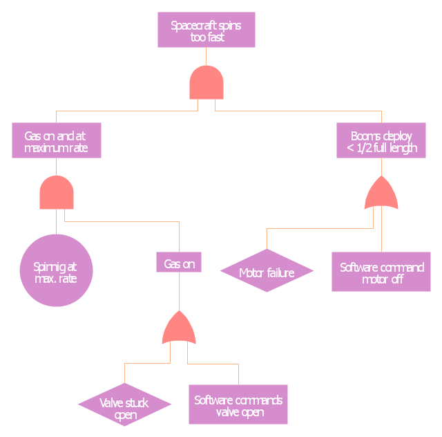
This example was redesigned from the Wikimedia Commons file: Example of High Level Fault Tree.jpg. [commons.wikimedia.org/ wiki/ File:Example_ of_ High_ Level_ Fault_ Tree.jpg]
"Risk assessment is the determination of quantitative or qualitative value of risk related to a concrete situation and a recognized threat (also called hazard). Quantitative risk assessment requires calculations of two components of risk (R):, the magnitude of the potential loss (L), and the probability (p) that the loss will occur. Acceptable risk is a risk that is understood and tolerated usually because the cost or difficulty of implementing an effective countermeasure for the associated vulnerability exceeds the expectation of loss.
In all types of engineering of complex systems sophisticated risk assessments are often made within Safety engineering and Reliability engineering when it concerns threats to life, environment or machine functioning. The nuclear, aerospace, oil, rail and military industries have a long history of dealing with risk assessment. Also, medical, hospital, social service and food industries control risks and perform risk assessments on a continual basis. Methods for assessment of risk may differ between industries and whether it pertains to general financial decisions or environmental, ecological, or public health risk assessment." [Risk assessment. Wikipedia]
The FTA diagram example "High level fault tree" was created using the ConceptDraw PRO diagramming and vector drawing software extended with the Fault Tree Analysis Diagrams solution from the Engineering area of ConceptDraw Solution Park.
FTA diagram
Mechanical Design Software

Mechanical Drawing Symbols

Process Flow Diagram Symbols

Process and Instrumentation Diagram

Mechanical Engineering

Mechanical Drawing Software

 Mechanical Engineering
This solution extends ConceptDraw PRO v.9 mechanical drawing software (or later) with samples of mechanical drawing symbols, templates and libraries of design elements, for help when drafting mechanical engineering drawings, or parts, assembly, pneumatic,
Process Diagrams

Chemical Engineering

Process Engineering

Electrical Symbols — Electrical Circuits

 Plumbing and Piping Plans
Plumbing and Piping Plans solution extends ConceptDraw PRO v10.2.2 software with samples, templates and libraries of pipes, plumbing, and valves design elements for developing of water and plumbing systems, and for drawing Plumbing plan, Piping plan, PVC Pipe plan, PVC Pipe furniture plan, Plumbing layout plan, Plumbing floor plan, Half pipe plans, Pipe bender plans.
- Fault Tree Analysis Diagrams | PROBLEM ANALYSIS. Root Cause ...
- Fault tree analysis diagram template | Process Flowchart | Project ...
- Root cause analysis tree diagram - Template | Fault Tree Analysis ...
- Fault Tree Analysis Template
- Fault Tree Analysis Diagrams | PROBLEM ANALYSIS. Root Cause ...
- How to Create a Fault Tree Analysis Diagram (FTD) in ConceptDraw ...
- Fault Tree Analysis Software
- Fault Tree Analysis Diagrams
- Fault tree analysis diagram template | Circular Arrows Diagrams ...
- Fault Tree Analysis Diagrams | Tree Network Topology Diagram ...
- Design elements - Fault tree analysis diagrams | Audit failure - Fault ...
- Fault Tree Analysis Software | Fault tree analysis diagram template ...
- FTA diagram - Hazard analysis | Accident analytic tree - FTA ...
- How to Create a Fault Tree Analysis Diagram (FTD) in ConceptDraw ...
- Process Flowchart | Fault Tree Analysis Software | ATM UML ...
- ConceptDraw Solution Park | Fault Tree Analysis Diagrams | How To ...
- How to Create a Fault Tree Analysis Diagram (FTD) in ConceptDraw ...
- Fault Tree Analysis Software Open Source
- Active Directory Diagram | Fault Tree Analysis Diagrams | Physics ...
- How to Create a Fault Tree Analysis Diagram (FTD) in ConceptDraw ...