Building Plans with ConceptDraw PRO
Building Drawing Software for Design Seating Plan


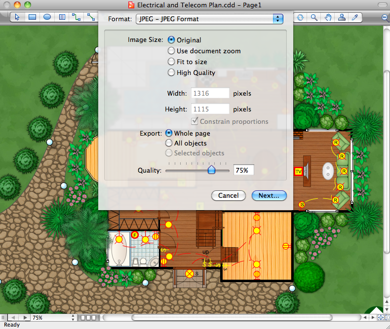
Home Design Software

Piping and Instrumentation Diagram Software

Building Drawing Design Element: Piping Plan

 Website Wireframe
The innovative Website Wireframe solution enhances the ConceptDraw PRO v10 functionality with newest wireframe tools, libraries with variety of predesigned icons, symbols, buttons, graphics, forms, boxes, and many other vector elements, templates and professionally designed samples, which make it the best wireframing software. Website Wireframe solution gives you significant advantages when designing and maintaining websites, creating skeletal and content-free depictions of website structure, making website prototypes and planning the content arrangement before committing to design, also speeds up the processes of sketching, producing and sharing wireframe examples of website style and interface design.
Types of Flowcharts


Electrical Symbols — MOSFET

Fishbone Diagram Problem Solving

Technical Flow Chart

- Design elements - Stations | Plant Layout Plans | Design elements ...
- Atmosphere air composition | Percentage Pie Chart. Pie Chart ...
- Lighting - Vector stencils library | Visible light communication | Status ...
- Lighting - Vector stencils library | Design elements - Optics | Optics ...
- Ray tracing diagram for convex lens
- Fire Exit Plan . Building Plan Examples | Emergency Plan | Simple ...
- Energy resources diagram | Network Diagram Software (PRO ...
- How To Draw Building Plans | Technical Drawing Software ...
- Office Layout Plans | Building Drawing Software for Design Office ...