Electrical Symbols — Electrical Circuits

Accounting Flowchart Symbols

Electrical Symbols — IGFET

Electrical Symbols — Integrated Circuit

Electrical Symbols, Electrical Diagram Symbols

Process Flowchart


The vector stencils library "Switches and relays" contains 58 symbols of electrical contacts, switches, relays, circuit breakers, selectors, connectors, disconnect devices, switching circuits, current regulators, and thermostats for electrical devices.
"In electrical engineering, a switch is an electrical component that can break an electrical circuit, interrupting the current or diverting it from one conductor to another.
The most familiar form of switch is a manually operated electromechanical device with one or more sets of electrical contacts, which are connected to external circuits. Each set of contacts can be in one of two states: either "closed" meaning the contacts are touching and electricity can flow between them, or "open", meaning the contacts are separated and the switch is nonconducting. The mechanism actuating the transition between these two states (open or closed) can be either a "toggle" (flip switch for continuous "on" or "off") or "momentary" (push-for "on" or push-for "off") type.
A switch may be directly manipulated by a human as a control signal to a system, such as a computer keyboard button, or to control power flow in a circuit, such as a light switch. Automatically operated switches can be used to control the motions of machines, for example, to indicate that a garage door has reached its full open position or that a machine tool is in a position to accept another workpiece. Switches may be operated by process variables such as pressure, temperature, flow, current, voltage, and force, acting as sensors in a process and used to automatically control a system. ... A switch that is operated by another electrical circuit is called a relay. Large switches may be remotely operated by a motor drive mechanism. Some switches are used to isolate electric power from a system, providing a visible point of isolation that can be padlocked if necessary to prevent accidental operation of a machine during maintenance, or to prevent electric shock." [Switch. Wikipedia]
"A relay is an electrically operated switch. Many relays use an electromagnet to mechanically operate a switch, but other operating principles are also used, such as solid-state relays. Relays are used where it is necessary to control a circuit by a low-power signal (with complete electrical isolation between control and controlled circuits), or where several circuits must be controlled by one signal. The first relays were used in long distance telegraph circuits as amplifiers: they repeated the signal coming in from one circuit and re-transmitted it on another circuit. Relays were used extensively in telephone exchanges and early computers to perform logical operations.
A type of relay that can handle the high power required to directly control an electric motor or other loads is called a contactor. Solid-state relays control power circuits with no moving parts, instead using a semiconductor device to perform switching. Relays with calibrated operating characteristics and sometimes multiple operating coils are used to protect electrical circuits from overload or faults; in modern electric power systems these functions are performed by digital instruments still called "protective relays"." [Relay. Wikipedia]
The shapes example "Design elements - Switches and relays" was drawn using the ConceptDraw PRO diagramming and vector drawing software extended with the Electrical Engineering solution from the Engineering area of ConceptDraw Solution Park.
Switch and relay symbols

Local area network (LAN). Computer and Network Examples
. Computer and Network Examples")

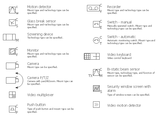
The vector stencils library Video surveillance contains 15 symbols of electronic closed-circuit television (CCTV) equipment, digital video cameras and recording devices and covert video equipment.
"Closed-circuit television (CCTV) is the use of video cameras to transmit a signal to a specific place, on a limited set of monitors. It differs from broadcast television in that the signal is not openly transmitted, though it may employ point to point (P2P), point to multipoint, or mesh wireless links. Though almost all video cameras fit this definition, the term is most often applied to those used for surveillance in areas that may need monitoring such as banks, casinos, airports, military installations, and convenience stores.
In industrial plants, CCTV equipment may be used to observe parts of a process from a central control room, for example when the environment is not suitable for humans. CCTV systems may operate continuously or only as required to monitor a particular event. A more advanced form of CCTV, utilizing digital video recorders (DVRs), provides recording for possibly many years, with a variety of quality and performance options and extra features (such as motion-detection and email alerts). More recently, decentralized IP cameras, some equipped with megapixel sensors, support recording directly to network-attached storage devices, or internal flash for completely stand-alone operation. Surveillance of the public using CCTV is particularly common in many areas around the world." [Closed-circuit television. Wikipedia]
Use the design elements library Video surveillance to design the layout plans of security and access systems, and internal and external video surveillance and security control monitoring systems using the ConceptDraw PRO diagramming and vector drawing software.
The shapes library Video surveillance is included in the Security and Access Plans solution from the Building Plans area of ConceptDraw Solution Park.
Video surveillance symbols
Block Diagram

Network Diagram Software LAN Network Diagrams & Diagrams for LAN Physical Office Network Diagrams

Network wiring cable. Computer and Network Examples

Diagramming Software for Design UML Collaboration Diagrams


- Mechanical All Parts Drawing Symbol With Meaning Use
- Electrical Symbols — Electrical Circuits | Process Flowchart ...
- Electrical Engineering Drawing Circuit Components
- Basic Flowchart Symbols and Meaning | ERD Symbols and ...
- Electronics Circuit Symbols And Functions Pdf
- Process Flow Diagram Symbols | Electrical Symbols , Electrical ...
- Electrical Devices And Circuit All Symbols Image Download
- Electricity And Circuit Meaning
- Electric Circuit Components And Their Symbol And Their Task
- Fault Tree Analysis Symbol Meaning
- How To use House Electrical Plan Software | Electrical Symbols ...
- Basic Flowchart Symbols and Meaning | Accounting Flowchart ...
- Electrical Symbols , Electrical Diagram Symbols | Home Electrical ...
- Circuit Symbols
- Electrical Symbols , Electrical Diagram Symbols | Electrical Symbols ...
- Process Flow Diagram Symbols | ERD Symbols and Meanings ...
- Process Flowchart | Basic Flowchart Symbols and Meaning | ERD ...
- Accounting Flowchart Symbols | Electrical Symbols — Electrical ...
- Symbol Of All Electronic Device In Pdf
- Mechanical Drawing Symbols | Entity Relationship Diagram ...