Electrical Symbols, Electrical Diagram Symbols

Electrical Drawing Software and Electrical Symbols

Electrical Symbols — Analog and Digital Logic

Piping and Instrumentation Diagram Software

The vector stencils library "Lamps, acoustics, readouts" contains 35 element symbols of lamps, acoustic components, electrical measuring instruments for drawing electrical schematics and electronic circuit diagrams.
"Electrical measurements are the methods, devices and calculations used to measure electrical quantities. Measurement of electrical quantities may be done to measure electrical parameters of a system. Using transducers, physical properties such as temperature, pressure, flow, force, and many others can be converted into electrical signals, which can then be conveniently measured and recorded." [Electrical measurements. Wikipedia]
"A lamp is a replaceable component such as an incandescent light bulb, which is designed to produce light from electricity." [Lamp (electrical component). Wikipedia]
"An electric bell is a mechanical bell that... functions by means of an electromagnet. When an electric current is applied, it produces a repetitive buzzing or clanging sound." [Electric bell. Wikipedia]
"A buzzer or beeper is an audio signalling device, which may be mechanical, electromechanical, or piezoelectric." [Buzzer. Wikipedia]
"Electronic sirens incorporate circuits such as oscillators, modulators, and amplifiers to synthesize a selected siren tone (wail, yelp, pierce/ priority/ phaser, hi-lo, scan, airhorn, manual, and a few more) which is played through external speakers." [Siren (noisemaker). Wikipedia]
"A microphone (colloquially called a mic or mike...) is an acoustic-to-electric transducer or sensor that converts sound in air into an electrical signal. ...
Most microphones today use electromagnetic induction (dynamic microphone), capacitance change (condenser microphone) or piezoelectric generation to produce an electrical signal from air pressure variations." [Microphone. Wikipedia]
The symbols example "Design elements - Lamps, acoustics, readouts" was drawn using the ConceptDraw PRO diagramming and vector drawing software extended with the Electrical Engineering solution from the Engineering area of ConceptDraw Solution Park.
Lamps, acoustics, electrical measuring instruments

 Telecommunication Network Diagrams
Telecommunication Network Diagrams solution extends ConceptDraw DIAGRAM software with samples, templates, and great collection of vector stencils to help the specialists in a field of networks and telecommunications, as well as other users to create Computer systems networking and Telecommunication network diagrams for various fields, to organize the work of call centers, to design the GPRS networks and GPS navigational systems, mobile, satellite and hybrid communication networks, to construct the mobile TV networks and wireless broadband networks.
The vector stencils library "Transmission paths" contains 43 symbols of power transmission paths, electronic circuits, bus connectors and elbows, terminals, junctions, and concentrators.
Use it to annotate electrical diagrams, electronic schematics and circuit diagrams.
"A physical medium in data communications is the transmission path over which a signal propagates.
Many transmission media are used as communications channel.
For telecommunications purposes in the United States, Federal Standard 1037C, transmission media are classified as one of the following:
(1) Guided (or bounded) - waves are guided along a solid medium such as a transmission line.
(2) Wireless (or unguided) - transmission and reception are achieved by means of an antenna.
One of the most common physical medias used in networking is copper wire. Copper wire to carry signals to long distances using relatively low amounts of power. The unshielded twisted pair (UTP) is eight strands of copper wire, organized into four pairs.
Another example of a physical medium is optical fiber, which has emerged as the most commonly used transmission medium for long-distance communications. Optical fiber is a thin strand of glass that guides light along its length.
Multimode and single mode are two types of commonly used optical fiber. Multimode fiber uses LEDs as the light source and can carry signals over shorter distances, about 2 kilometers. Single mode can carry signals over distances of tens of miles.
Wireless media may carry surface waves or skywaves, either longitudinally or transversely, and are so classified.
In both communications, communication is in the form of electromagnetic waves. With guided transmission media, the waves are guided along a physical path; examples of guided media include phone lines, twisted pair cables, coaxial cables, and optical fibers. Unguided transmission media are methods that allow the transmission of data without the use of physical means to define the path it takes. Examples of this include microwave, radio or infrared. Unguided media provide a means for transmitting electromagnetic waves but do not guide them; examples are propagation through air, vacuum and seawater.
The term direct link is used to refer to the transmission path between two devices in which signals propagate directly from transmitters to receivers with no intermediate devices, other than amplifiers or repeaters used to increase signal strength. This term can apply to both guided and unguided media.
A transmission may be simplex, half-duplex, or full-duplex.
In simplex transmission, signals are transmitted in only one direction; one station is a transmitter and the other is the receiver. In the half-duplex operation, both stations may transmit, but only one at a time. In full duplex operation, both stations may transmit simultaneously. In the latter case, the medium is carrying signals in both directions at same time." [Transmission medium. Wikipedia]
The shapes example "Design elements - Transmission paths" was drawn using the ConceptDraw PRO diagramming and vector drawing software extended with the Electrical Engineering solution from the Engineering area of ConceptDraw Solution Park.
Transmission path symbols

Electrical Symbols — Lamps, Acoustics, Readouts

Electrical Symbols — Logic Gate Diagram

Electrical Symbols — Transformers and Windings

The vector stencils library "Cisco optical" contains 19 symbols of optical devices for drawing Cisco computer network diagrams.
"Fiber-optic communication is a method of transmitting information from one place to another by sending pulses of light through an optical fiber. The light forms an electromagnetic carrier wave that is modulated to carry information. ... Because of its advantages over electrical transmission, optical fibers have largely replaced copper wire communications in core networks in the developed world. Optical fiber is used by many telecommunications companies to transmit telephone signals, Internet communication, and cable television signals. ...
The process of communicating using fiber-optics involves the following basic steps: Creating the optical signal involving the use of a transmitter, relaying the signal along the fiber, ensuring that the signal does not become too distorted or weak, receiving the optical signal, and converting it into an electrical signal." [Fiber-optic communication. Wikipedia]
The symbols example "Cisco optical - Vector stencils library" was created using the ConceptDraw PRO diagramming and vector drawing software extended with the Cisco Network Diagrams solution from the Computer and Networks area of ConceptDraw Solution Park.
www.conceptdraw.com/ solution-park/ computer-networks-cisco
Automatic Protection Switching (APS)
-cisco-optical---vector-stencils-library.png--diagram-flowchart-example.png)
Channelized pipe

Concatenated payload

Optical cross-connect

WDM

Optical fiber

ONS 15104

SONET MUX

Optical amplifier

Digitall cross-connect

Optical services router

Cisco 10700

Optical transport

Wide Area Application Engine (WAE)
-cisco-optical---vector-stencils-library.png--diagram-flowchart-example.png)
Protected optical

Unprotected optical

Metro 1500

ONS 15500

Pipe

Point-to-multipoint (P2MP) Network. Computer and Network Examples
 Network. <br>Computer and Network Examples *")

The vector stencils library "Rack diagrams" contains 33 rack design elements for drawing the computer network server rack diagrams.
"A 19-inch rack is a standardized frame or enclosure for mounting multiple equipment modules. Each module has a front panel that is 19 inches (482.6 mm) wide, including edges or ears that protrude on each side which allow the module to be fastened to the rack frame with screws. ...
Equipment designed to be placed in a rack is typically described as rack-mount, rack-mount instrument, a rack mounted system, a rack mount chassis, subrack, rack mountable, or occasionally simply shelf. The height of the electronic modules is also standardized as multiples of 1.75 inches (44.45 mm) or one rack unit or U (less commonly RU). The industry standard rack cabinet is 42U tall. ...
19-inch racks in 2-post or 4-post form hold most equipment in modern data centers, ISP facilities and professionally designed corporate server rooms. They allow for dense hardware configurations without occupying excessive floorspace or requiring shelving." [19-inch rack. Wikipedia]
The clip art example "Rack diagrams - Vector stencils library" was created using the ConceptDraw PRO diagramming and vector drawing software extended with the Rack Diagrams solution from the Computer and Networks area of ConceptDraw Solution Park.
19 inch Rack with Rails

Rack

Rack rails

Rack rails (half-width)
-rack-diagrams---vector-stencils-library.png--diagram-flowchart-example.png)
Single rack rail

Xserve RAID

XServe

1U tray

1U spacer

2U server

1U Ethernet Switch/Hub

2U Ethernet Switch/Hub

1U power strip

1U KVM switch

1U patch panel

Rackmount UPS

Cisco switch (WS-C3560-24PS-S)
-rack-diagrams---vector-stencils-library.png--diagram-flowchart-example.png)
Cisco switch (WS-C3560-48TS-S)
-rack-diagrams---vector-stencils-library.png--diagram-flowchart-example.png)
Cisco switch (WS-C2960-48TT-L)
-rack-diagrams---vector-stencils-library.png--diagram-flowchart-example.png)
Cisco switch (WS-C2960-48TC-L)
-rack-diagrams---vector-stencils-library.png--diagram-flowchart-example.png)
Cisco switch (WS-C2960-24TT-L)
-rack-diagrams---vector-stencils-library.png--diagram-flowchart-example.png)
Cisco switch (WS-C2960-24TC-L)
-rack-diagrams---vector-stencils-library.png--diagram-flowchart-example.png)
7U rackmount LCD monitor

8U rackmount LCD monitor

Fiber optic patch panel (type A)
-rack-diagrams---vector-stencils-library.png--diagram-flowchart-example.png)
Fiber optic patch panel (type B)
-rack-diagrams---vector-stencils-library.png--diagram-flowchart-example.png)
Fiber optic patch panel (type C)
-rack-diagrams---vector-stencils-library.png--diagram-flowchart-example.png)
3U server

2U RAID array

3U RAID array

Managed UPS

1U 19'' LCD monitor keyboard

1U server

Electrical Symbols — Composite Assemblies

 Health Sciences
Health Sciences solution including professionally designed samples and wide range of high-quality vector icons and pictograms of basic medical sciences, surgery specializations, internal medicine, medical diagnostics, interdisciplinary fields, mental health, obstetrics and gynecology, public health, allied health, and other medical specialties, is a perfect assistant in drawing Health diagrams, schematics, illustrations, infographics and slides for presentations on the healthcare, medical and health sciences thematic, in development knowledge in health science, in studying and representing the physical, mental and social aspects of human health, in determining the role of different health sciences at this process, finding and explaining new methods of treatment different diseases, making an overview and describing the main characteristics of health sciences in a visual form.
The vector stencils library "Telecom equipment" contains 11 hardware clipart icons of telecommunication devices for drawing computer network diagrams and equipment layouts.
"In telecommunication, a communications system is a collection of individual communications networks, transmission systems, relay stations, tributary stations, and data terminal equipment (DTE) usually capable of interconnection and interoperation to form an integrated whole. The components of a communications system serve a common purpose, are technically compatible, use common procedures, respond to controls, and operate in union. Telecommunications is a method of communication." [Communications system. Wikipedia]
"A basic telecommunication system consists of three primary units that are always present in some form: (1) A transmitter that takes information and converts it to a signal. (2) A transmission medium, also called the "physical channel" that carries the signal. ... (3) A receiver that takes the signal from the channel and converts it back into usable information." [Telecommunication. Wikipedia]
The clip art example "Telecom equipment - Vector stencils library" was created using the ConceptDraw PRO diagramming and vector drawing software extended with the Telecommunication Network Diagrams solution from the Computer and Networks area of ConceptDraw Solution Park.
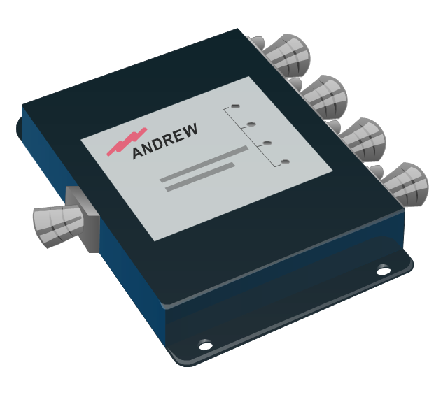
Andrew multiband high / low power splitter
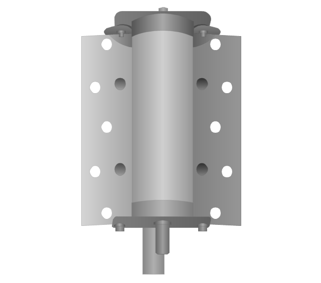
Andrew multi-band indoor omnidirectional antenna

Panel sector directional antenna
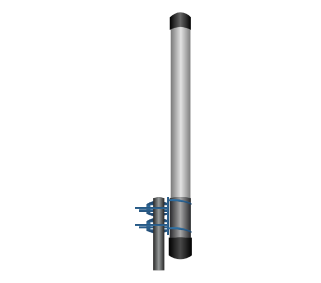
Omni directional antenna
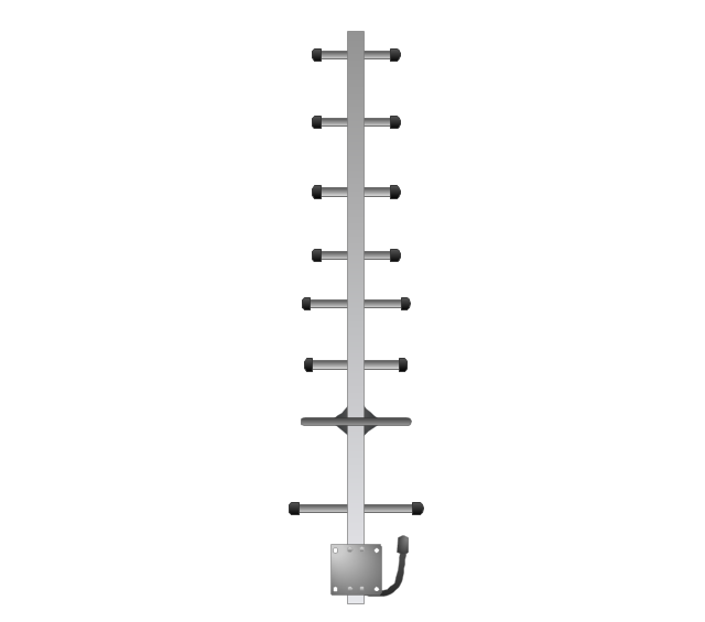
Yagi directional antenna
Yagi integrated downconverter
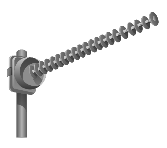
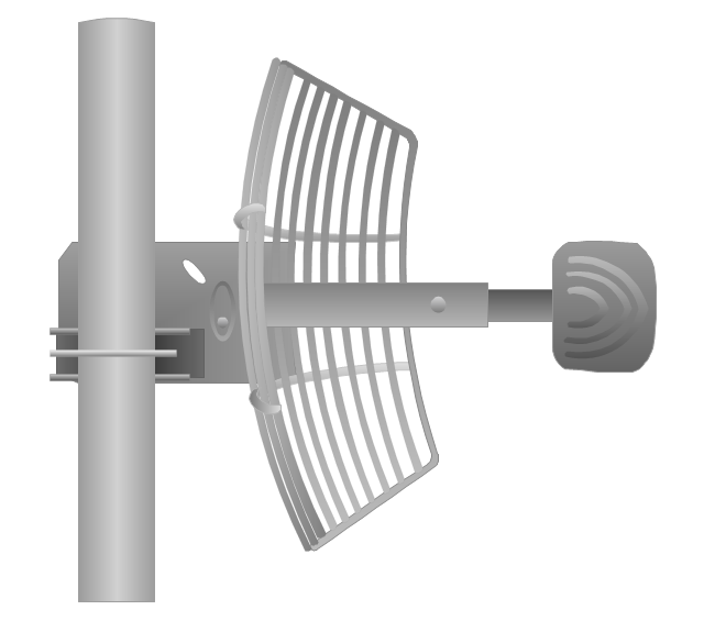
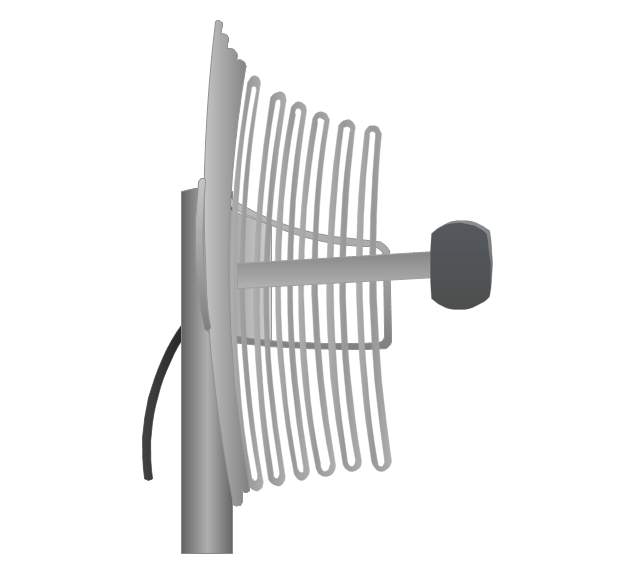
Grid antenna
Loop antenna
FireTide HotPort® 6000 wireless mesh nodes
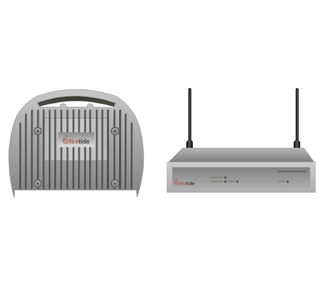
FireTide HotPoint® wireless access point
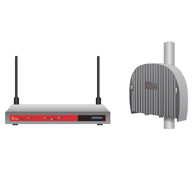
FireTide HotClient Customer Premises Equipment (CPE)
-telecom-equipment---vector-stencils-library.png--diagram-flowchart-example.png)
The vector stencils library "Switches and relays" contains 58 symbols of electrical contacts, switches, relays, circuit breakers, selectors, connectors, disconnect devices, switching circuits, current regulators, and thermostats for electrical devices.
"In electrical engineering, a switch is an electrical component that can break an electrical circuit, interrupting the current or diverting it from one conductor to another.
The most familiar form of switch is a manually operated electromechanical device with one or more sets of electrical contacts, which are connected to external circuits. Each set of contacts can be in one of two states: either "closed" meaning the contacts are touching and electricity can flow between them, or "open", meaning the contacts are separated and the switch is nonconducting. The mechanism actuating the transition between these two states (open or closed) can be either a "toggle" (flip switch for continuous "on" or "off") or "momentary" (push-for "on" or push-for "off") type.
A switch may be directly manipulated by a human as a control signal to a system, such as a computer keyboard button, or to control power flow in a circuit, such as a light switch. Automatically operated switches can be used to control the motions of machines, for example, to indicate that a garage door has reached its full open position or that a machine tool is in a position to accept another workpiece. Switches may be operated by process variables such as pressure, temperature, flow, current, voltage, and force, acting as sensors in a process and used to automatically control a system. ... A switch that is operated by another electrical circuit is called a relay. Large switches may be remotely operated by a motor drive mechanism. Some switches are used to isolate electric power from a system, providing a visible point of isolation that can be padlocked if necessary to prevent accidental operation of a machine during maintenance, or to prevent electric shock." [Switch. Wikipedia]
"A relay is an electrically operated switch. Many relays use an electromagnet to mechanically operate a switch, but other operating principles are also used, such as solid-state relays. Relays are used where it is necessary to control a circuit by a low-power signal (with complete electrical isolation between control and controlled circuits), or where several circuits must be controlled by one signal. The first relays were used in long distance telegraph circuits as amplifiers: they repeated the signal coming in from one circuit and re-transmitted it on another circuit. Relays were used extensively in telephone exchanges and early computers to perform logical operations.
A type of relay that can handle the high power required to directly control an electric motor or other loads is called a contactor. Solid-state relays control power circuits with no moving parts, instead using a semiconductor device to perform switching. Relays with calibrated operating characteristics and sometimes multiple operating coils are used to protect electrical circuits from overload or faults; in modern electric power systems these functions are performed by digital instruments still called "protective relays"." [Relay. Wikipedia]
The shapes example "Design elements - Switches and relays" was drawn using the ConceptDraw PRO diagramming and vector drawing software extended with the Electrical Engineering solution from the Engineering area of ConceptDraw Solution Park.
Switch and relay symbols

The vector stencils library Initiation and annunciation contains 9 symbols of Fire Alarm Control Panel (FACP) or Fire Alarm Control Unit (FACU) elements, triggering devices, audible alarm systems, timers, security control equipment, and recording devices.
"A Fire Alarm Control Panel (FACP), or Fire Alarm Control Unit (FACU), is the controlling component of a Fire Alarm System. The panel receives information from environmental sensors designed to detect changes associated with fire, monitors their operational integrity and provides for automatic control of equipment, and transmission of information necessary to prepare the facility for fire based on a predetermined sequence. The panel may also supply electrical energy to operate any associated sensor, control, transmitter, or relay. There are four basic types of panels: coded panels, conventional panels, addressable panels, and multiplex systems." [Fire alarm control panel. Wikipedia]
Use the shapes library Initiation and annunciation to draw layout floor plans, communications schematics and wiring diagrams of security systems using the ConceptDraw PRO diagramming and vector drawing software.
The design elements library Initiation and annunciation is included in the Security and Access Plans solution from the Building Plans area of ConceptDraw Solution Park.
Initiation and annunciation symbols

This cafe electrical floor plan sample shows the outlet and switch layout.
"An electrical drawing, is a type of technical drawing that shows information about power, lighting, and communication for an engineering or architectural project. Any electrical working drawing consists of "lines, symbols, dimensions, and notations to accurately convey an engineering's design to the workers, who install the electrical system on the job".
A complete set of working drawings for the average electrical system in large projects usually consists of:
(1) A plot plan showing the building's location and outside electrical wiring.
(2) Floor plans showing the location of electrical systems on every floor.
(3) Power-riser diagrams showing panel boards.
(4) Control wiring diagrams.
(5) Schedules and other information in combination with construction drawings.
Electrical drafters prepare wiring and layout diagrams used by workers who erect, install, and repair electrical equipment and wiring in communication centers, power plants, electrical distribution systems, and buildings." [Electrical drawing. Wikipedia]
The outlet and switch layout example "Cafe electrical floor plan" was created using the ConceptDraw PRO diagramming and vector drawing software extended with the Electric and Telecom Plans solution from the Building Plans area of ConceptDraw Solution Park.
Outlet and switch layout

The vector stencils library "Electrical circuits" contains 49 element symbols of electrical and electronic devices, including ignitors, starters, transmitters, circuit protectors, transducers, radio and audio equipment.
Use it for drawing electronic circuit diagrams and electrical schematics in the ConceptDraw PRO diagramming and vector drawing software extended with the Electrical Engineering solution from the Engineering area of ConceptDraw Solution Park.
www.conceptdraw.com/ solution-park/ engineering-electrical
Ground

Equipotentiality

Igniter plug

Junction

Chassis

Chassis 2

Capacitor

Variable capacitor

Capacitor 2

Variable capacitor 2

Antenna

Antenna 2

Circuit breaker

Fuse

Fuse 2

Alarm fuse

Alarm fuse 2

Circular generic component

Rectangular generic component

Transducer

Capacitive transducer

Non-capacitive transducer

Recording pickup head

Reproducing pickup head

Positive pulse

Negative pulse

Alternating pulse

Saw tooth

Positive step function

Negative step function

Explosive squib

Sensing link squib

Squib ignitor

Unspecified material

Solid material

Semiconducting material

Liquid

Insulating material

Gas

Electret

Surge protector

Multigap surge protector

Valve surge protector

Electrolytic surge protector

Carbon block surge protector

Protective gap surge protector

Sphere gap surge protector

Horn gap surge protector

Circuit breaker

- What Are Examples Of Electrical Drawing Instrument
- Process Flowchart | Electrical Symbols — Transmission Paths ...
- Electrical Symbols, Electrical Diagram Symbols | Electrical Symbols ...
- Electrical Symbols, Electrical Diagram Symbols | Design elements ...
- How To use House Electrical Plan Software | Design elements ...
- Electrical Symbols, Electrical Diagram Symbols | Electrical Symbols ...
- Electrical Symbols, Electrical Diagram Symbols | Mechanical ...
- Basic Flowchart Symbols and Meaning | Electrical Symbols ...
- Design elements - Lamps, acoustics, measuring instruments ...
- Process Flow Diagram Symbols | Piping and Instrumentation ...
- Electrical Symbols, Electrical Diagram Symbols | Design elements ...
- Lamps, acoustics, measuring instruments - Vector stencils library ...
- Electrical Symbols, Electrical Diagram Symbols | Star Network ...
- Diagram Of Electrical Measuring Instruments
- Electrical Symbols, Electrical Diagram Symbols | Electrcial ...
- Electrical Symbols, Electrical Diagram Symbols | Mechanical ...
- Electrical Symbols, Electrical Diagram Symbols | Lamps, acoustics ...
- Electrical Symbols, Electrical Diagram Symbols | Electrical Symbols ...
- Electrical Symbols, Electrical Diagram Symbols | Technical Drawing ...
- Interior Design Machines and Equipment - Design Elements ...