Process Flow Diagram Symbols
Mechanical Drawing Symbols

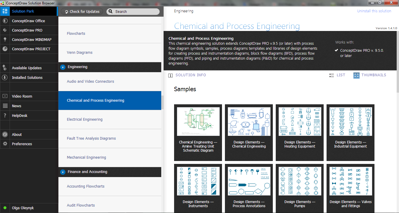
 Chemical and Process Engineering
This chemical engineering solution extends ConceptDraw DIAGRAM.9.5 (or later) with process flow diagram symbols, samples, process diagrams templates and libraries of design elements for creating process and instrumentation diagrams, block flow diagrams (BFD
Chemical Engineering

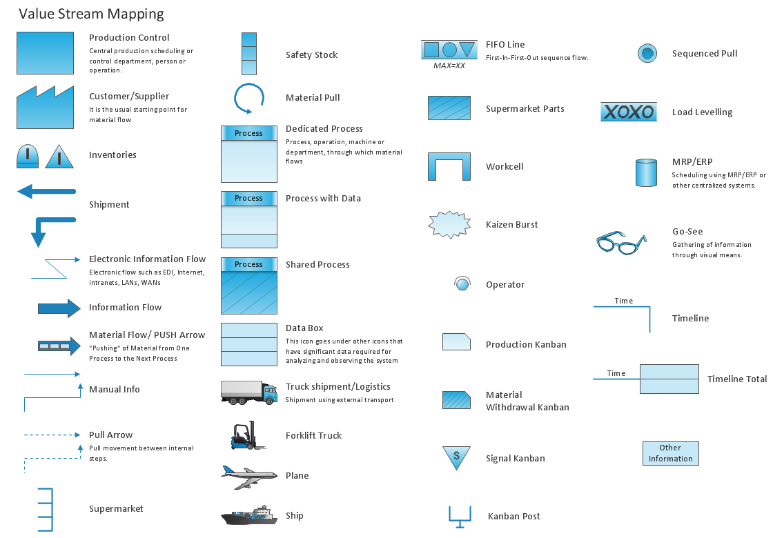
Value Stream Mapping Symbols
Electrical Symbols — Maintenance

Electrical Symbols — Logic Gate Diagram

Electrical Symbols — Delay Elements

Electrical Symbols — Analog and Digital Logic

Process Flow Chart

- Process Flow Diagram Symbols | Chemical and Process ...
- Process Flow Diagram Symbols | Appliances - Vector stencils library ...
- Chemical and Process Engineering | Cng Dryer Symbol
- Process Flow Diagram Symbols | Industrial equipment - Vector ...
- Horizontal Drum Dryer Equipment Symbol
- Design elements - Plumbing | Process Flow Diagram Symbols ...
- Design elements - HVAC control equipment | Process Flow Diagram ...
- Washer Dryer Floor Plan Icon
- Process Flow Diagram Symbols | Design elements - Appliances ...
- Process Flow Diagram Symbols | Pumps - Vector stencils library ...