HelpDesk
How to Create a Bar Chart in ConceptDraw PRO

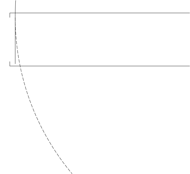
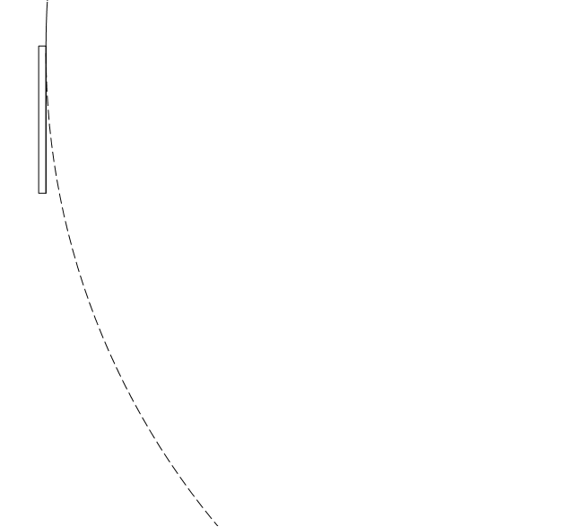
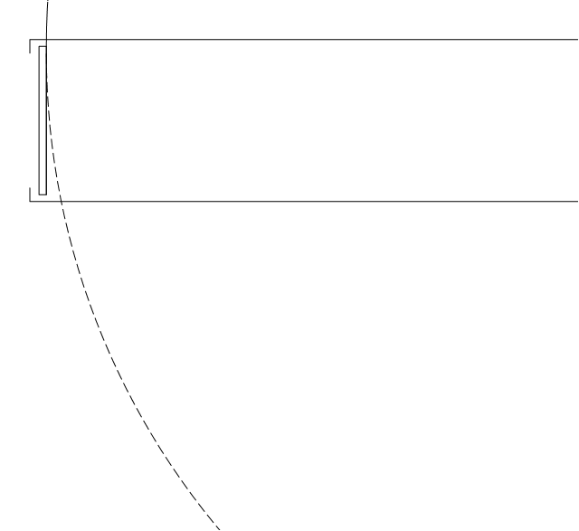
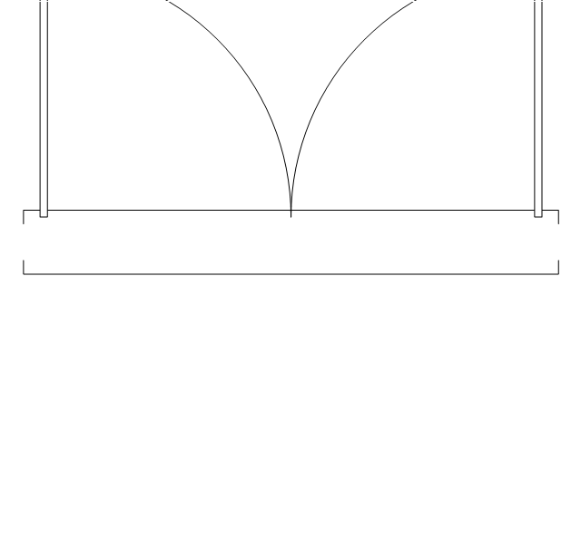
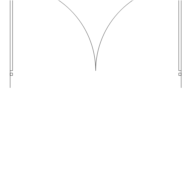
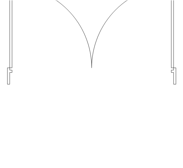
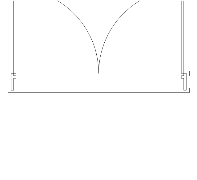
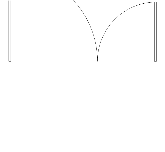
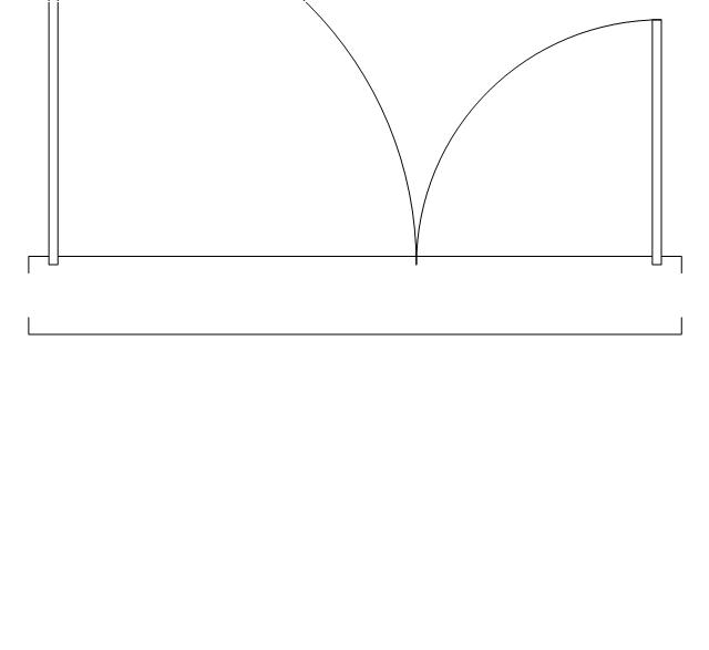
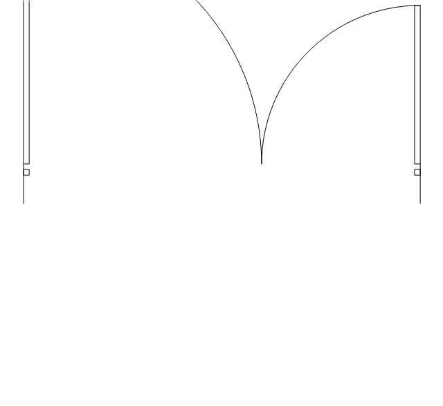
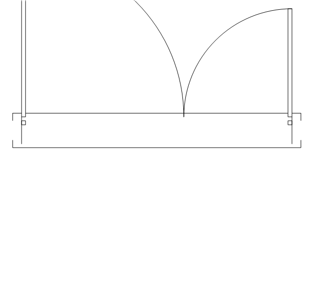
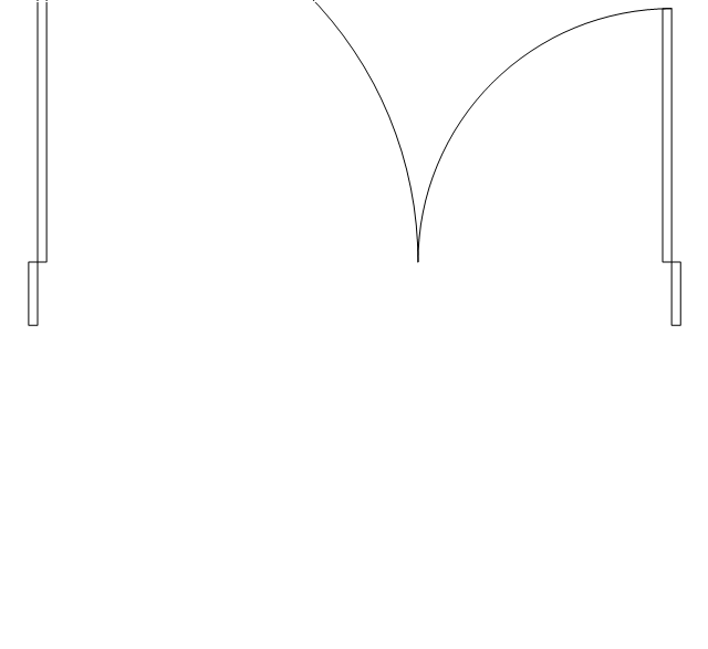
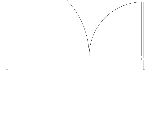
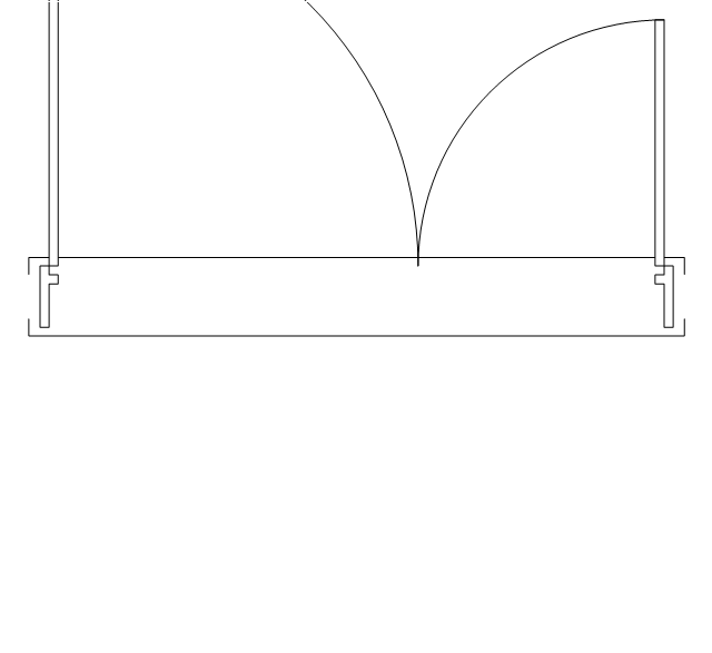
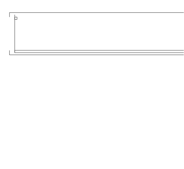
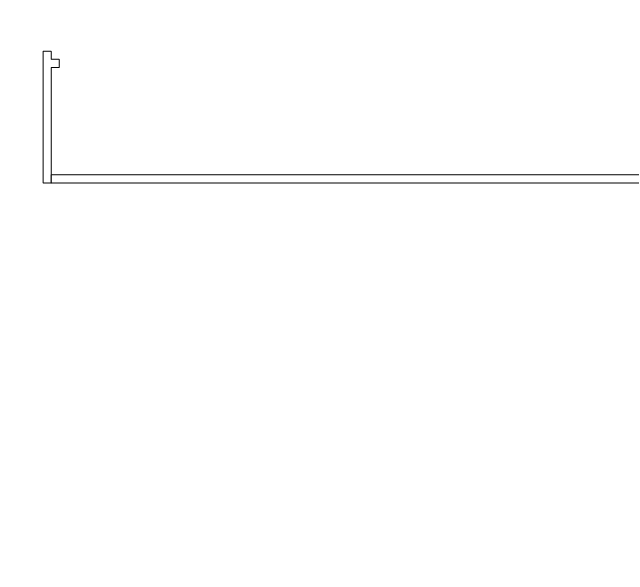
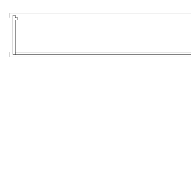
The vector stencils library "Doors" contains 69 shapes of doors. Use it for drawing floor plans in the ConceptDraw PRO diagramming and vector drawing software extended with the Floor Plans solution from the Building Plans area of ConceptDraw Solution Park.
Opening

Door

Door, threshold

Door, stop
Door, stop, threshold
Door, frame

Door, frame, threshold
Door, frame, stop

Door, frame, stop, threshold

Double hung
Double hung, threshold
Double hung, frame
Double hung, frame, threshold
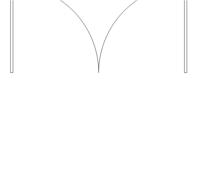
Double door
Double door, threshold
Double door, stop
Double door, stop, threshold
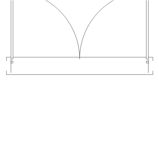
Double door, frame

Double door, frame, threshold
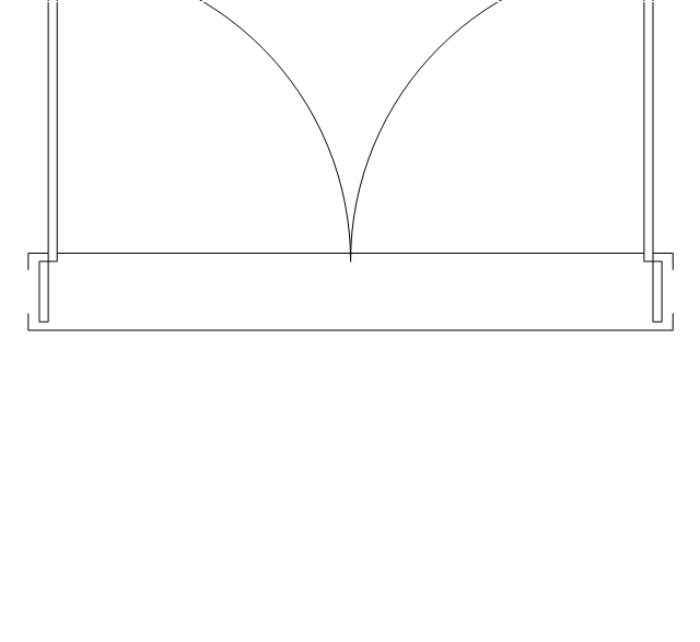
Double door, frame, stop
Double door, frame, stop, threshold
Uneven door
Uneven door, threshold
Uneven door, stop
Uneven door, stop, threshold
Uneven door, frame
Uneven door, frame, threshold

Uneven door, frame, stop
Uneven door, frame, stop, threshold
Opposing door

Opposing door, threshold

Opposing door, stop

Opposing door, stop, threshold
Opposing door, frame

Opposing door, frame, threshold

Opposing door, frame, stop
Opposing door, frame, stop, threshold
Revolving door
Revolving door, threshold
Revolving door, frame
Revolving door, frame, threshold
Pocket door

Pocket door, threshold
Pocket door, frame
Pocket door, frame, threshold
Dbl pocket door
Dbl pocket door, threshold
Dbl pocket door, frame
Dbl pocket door, frame, threshold
By-pass door
By-pass door, threshold

By-pass door, frame

By-pass door, frame, threshold

Bi-fold door
Bi-fold door, threshold
Bi-fold door, frame
Bi-fold door, frame, threshold
Double bi-fold door
Double bi-fold door, threshold
Double bi-fold door, frame
Double bi-fold door, frame, threshold
Sliding glass
Sliding glass, threshold
Sliding glass, frame
Sliding glass, frame, threshold
Overhead door

Overhead door, threshold
Overhead door, frame

Overhead door, frame, threshold
HelpDesk
How to Add a Self-Drawn Object to any Library

HelpDesk
How to Contribute Drawing With Library Objects

The vector stencils library "Welding" contains 38 welding joint symbols to identify fillets, contours, resistance seams, grooves, surfacing, and backing.
Use it to indicate welding operations on working drawings in the ConceptDraw PRO diagramming and vector drawing software extended with the Mechanical Engineering solution from the Engineering area of ConceptDraw Solution Park.
www.conceptdraw.com/ solution-park/ engineering-mechanical
Use it to indicate welding operations on working drawings in the ConceptDraw PRO diagramming and vector drawing software extended with the Mechanical Engineering solution from the Engineering area of ConceptDraw Solution Park.
www.conceptdraw.com/ solution-park/ engineering-mechanical
Additional arrow
Text block

Fillet

Slot / plug

Stud

Resistance seam

Backing

Surfacing

Flange corner

Flange edge

Square groove

V-groove

Bevel groove

U-groove

J-groove

Flare V groove

Flare bevel groove

Scarf

Melt through weld

Field weld

Backing / spacer

Insert

Arrow with bend
Arrow with bend, tail
Arrow with bend, circle
Arrow with bend, circle, tail
Arrow
Arrow, tail

Arrow, circle

Arrow, circle, tail

Spot

Projection weld

Contour, concave

Contour, convex

Contour, flush

Contour angled, concave

Contour angled, convex

Contour angled, flush

Square butt weld

Closed square butt weld

Single-bevel butt weld

Double-bevel butt weld

Single-V butt weld

Double-V butt weld

Single-J butt weld

Double-J butt weld

Single-U butt weld

Double-U butt weld

Flange butt weld

Tee butt weld

Flare butt weld

Square butt joint

Single V preparation joint

Lap joint

T-joint

Butt weld

Butt weld, single-V

Bilateral lap weld

Tee weld

Angular weld

Mechanical weld

HelpDesk
How to Create a Floor Plan Using ConceptDraw PRO

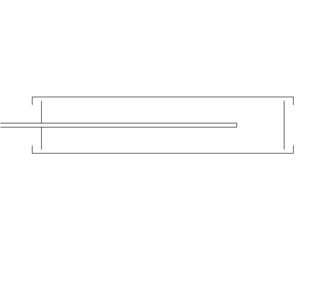
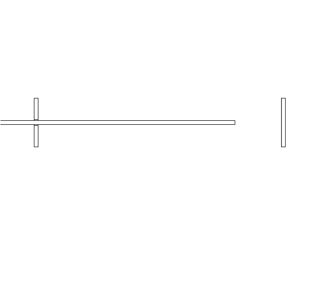
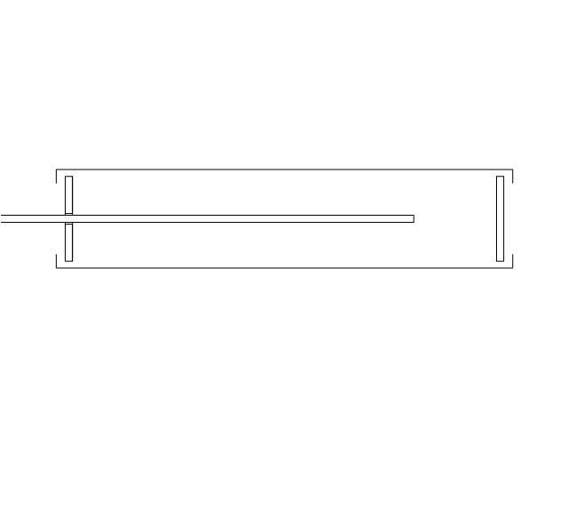
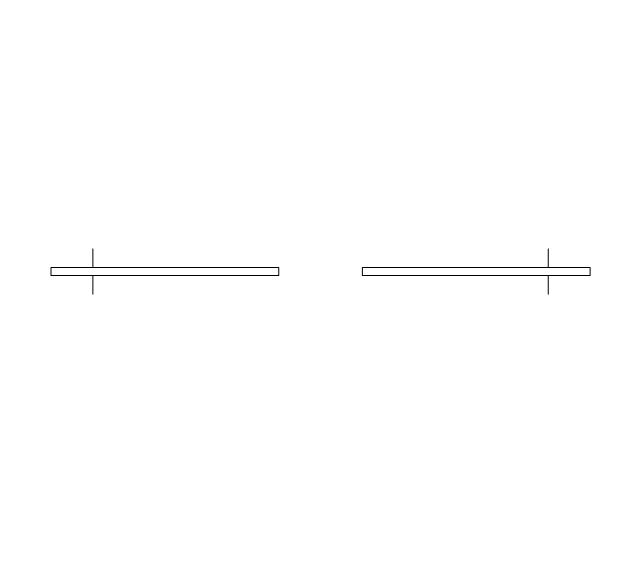
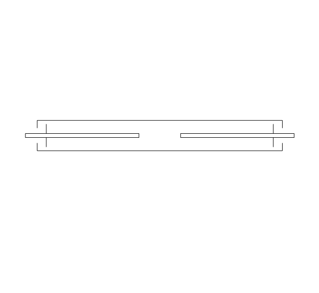
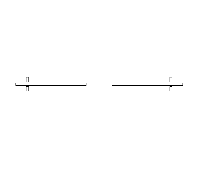
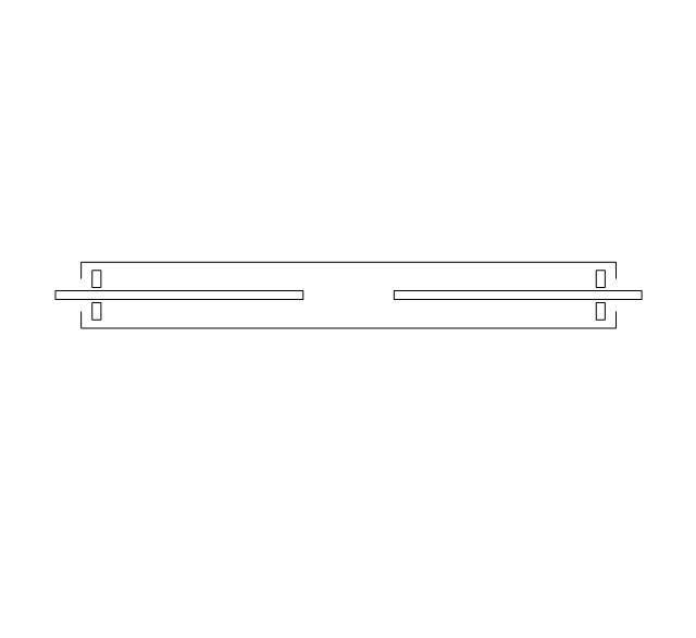
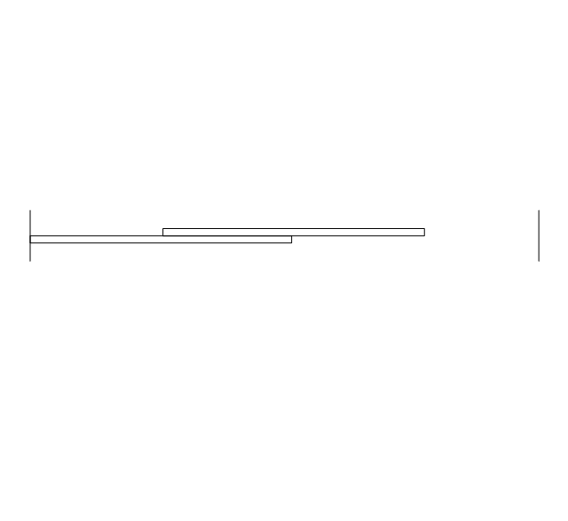
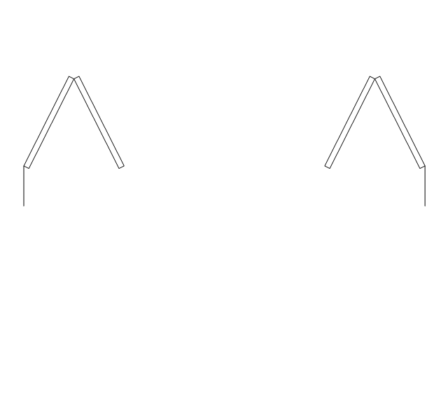
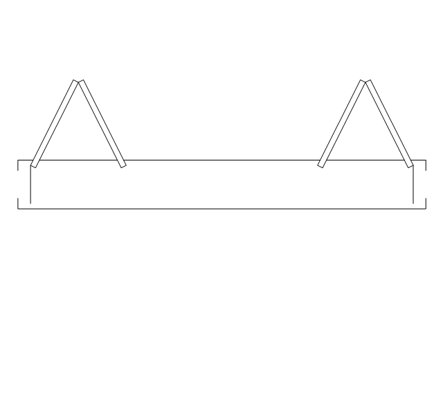
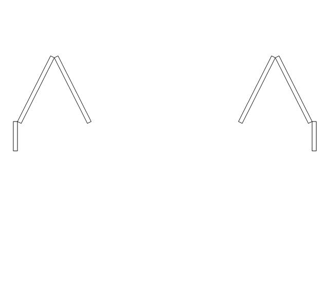
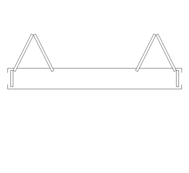
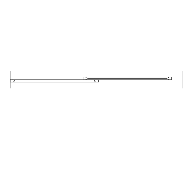
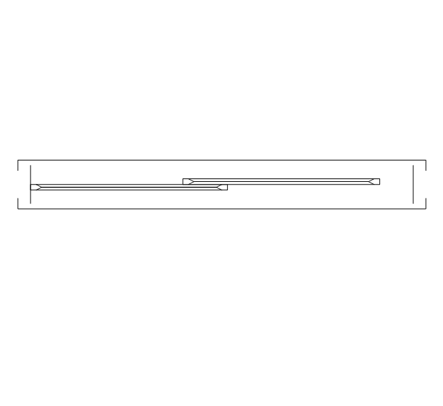
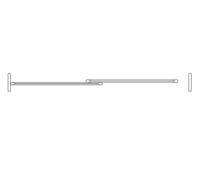
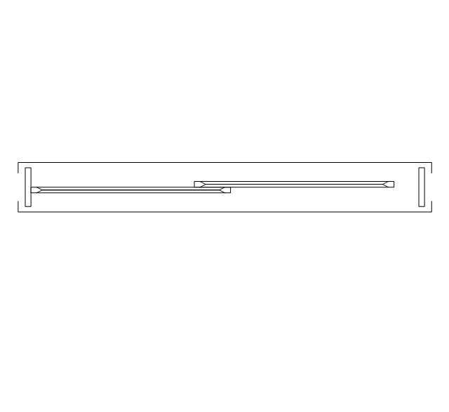
This engineering drawing shows different types of geometry of butt welds.
"Welds can be geometrically prepared in many different ways. The five basic types of weld joints are the butt joint, lap joint, corner joint, edge joint, and T-joint (a variant of this last is the cruciform joint). Other variations exist as well - for example, double-V preparation joints are characterized by the two pieces of material each tapering to a single center point at one-half their height. Single-U and double-U preparation joints are also fairly common - instead of having straight edges like the single-V and double-V preparation joints, they are curved, forming the shape of a U. Lap joints are also commonly more than two pieces thick - depending on the process used and the thickness of the material, many pieces can be welded together in a lap joint geometry." [Welding. Wikipedia]
This engineering drawing example was redesigned using the ConceptDraw PRO diagramming and vector drawing software from the Wikimedia Commons file: Butt Weld Geometry.GIF.
[commons.wikimedia.org/ wiki/ File:Butt_ Weld_ Geometry.GIF]
The engineering drawing example "Butt weld geometry" is included in the Mechanical Engineering solution from the Engineering area of ConceptDraw Solution Park.
Welding joint diagram

HelpDesk
How to Design a Food-related Infographics Using ConceptDraw PRO

- Common joint types | Welded joints types | Butt weld geometry ...
- Best Vector Drawing Application for Mac OS X | Offensive Play ...
- Symbol Of Double Hung Door
- Double V Butt Joint Drawing
- Offensive Play – Double Wing Wedge – Vector Graphic Diagram ...
- Design elements - School layout plan | Building Drawing Software ...
- Drawing Of Welding Joints
- Double Door Floor Plan
- Offensive Play – Double Wing Wedge – Vector Graphic Diagram ...
- Drawing Of Graph Template
- Give Five Examples Of Butt Joint With Drawings On Each
- Bathroom Drawing
- Welding symbols | Mechanical Drawing Symbols | Design elements ...
- Best Vector Drawing Application for Mac OS X | Rack diagrams ...
- Aromatics - Vector stencils library | Design elements - Conformations ...
- Architectural Drawing Of Casement Window In Plan
- Butt weld geometry | Design elements - Welding | Common joint ...
- Chemistry Drawings | Chemistry | Chemistry Drawing Software ...
- Double -headed Cross Functional Flowchart | Pipes 2 - Vector ...
- Chemistry | Chemistry Drawings | Solving quadratic equation ...