How To use House Electrical Plan Software


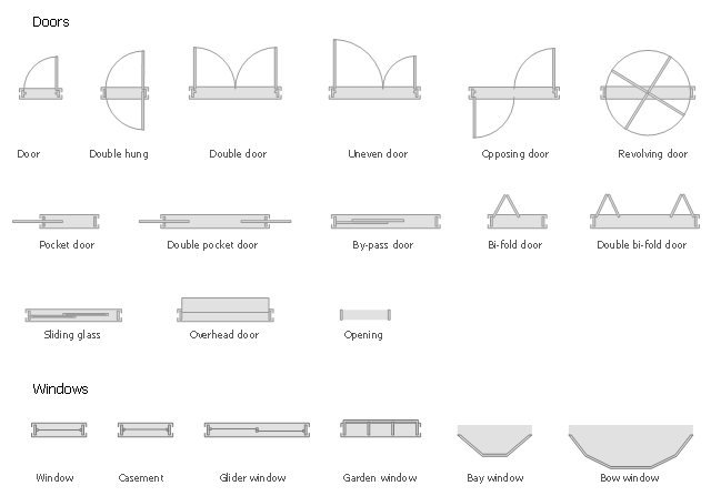
The design elements library Doors contains 69 symbols of doors.
The design elements library Windows contains 34 symbols of windows and casements.
"A door is an opening or closing structure used to block off an entrance, typically consisting of an interior side that faces the inside of a space and an exterior side that faces the outside of that space. While in some cases the interior side of a door may match its exterior side, in other cases there are sharp contrasts between the two sides, such as in the case of the vehicle door. In addition, doors typically consist of a panel that swings on hinges or that slides or spins inside of a space." [Door. Wikipedia]
"A window is an opening in a wall, door or vehicle that allows the passage of light and, if not closed or sealed, air and sound. Modern windows are usually glazed or covered in some other transparent or translucent material. Windows are held in place by frames. Many glazed windows may be opened, to allow ventilation, or closed, to exclude inclement weather." [Window. Wikipedia]
Use the shapes libraries Doors and Windows to create house plans, home plans, floor plan layouts and home designs using the ConceptDraw PRO diagramming and vector drawing software.
The vector stencils libraries Doors and Windows are provided by the Floor Plans solution from the Building Plans area of ConceptDraw Solution Park.
The vector stencils library Alarm and access control contains 80 symbols of digital proximity equipment, locking hardware, and access control equipment.
"An alarm device or system of alarm devices gives an audible, visual or other form of alarm signal about a problem or condition. Alarm devices are often outfitted with a siren." [Alarm device. Wikipedia]
"An access control point, which can be a door, turnstile, parking gate, elevator, or other physical barrier, where granting access can be electronically controlled. Typically, the access point is a door. An electronic access control door can contain several elements. At its most basic, there is a stand-alone electric lock. The lock is unlocked by an operator with a switch. To automate this, operator intervention is replaced by a reader. The reader could be a keypad where a code is entered, it could be a card reader, or it could be a biometric reader. Readers do not usually make an access decision, but send a card number to an access control panel that verifies the number against an access list. To monitor the door position a magnetic door switch can be used. In concept, the door switch is not unlike those on refrigerators or car doors. Generally only entry is controlled, and exit is uncontrolled. In cases where exit is also controlled, a second reader is used on the opposite side of the door. In cases where exit is not controlled, free exit, a device called a request-to-exit (REX) is used. Request-to-exit devices can be a push-button or a motion detector. When the button is pushed, or the motion detector detects motion at the door, the door alarm is temporarily ignored while the door is opened. Exiting a door without having to electrically unlock the door is called mechanical free egress. This is an important safety feature. In cases where the lock must be electrically unlocked on exit, the request-to-exit device also unlocks the door." [Access control. Wikipedia]
Use the design elements library Alarm and access control for drawing layout floor plans, blueprints, and wiring diagrams of intrusion systems, time and attendance systems, card and code access control security systems, internal and external security control systems using the ConceptDraw PRO diagramming and vector drawing software.
The shapes library Alarm and access control is included in the Security and Access Plans solution from the Building Plans area of ConceptDraw Solution Park.
Alarm and access control symbols

The design elements library Doors contains 69 symbols of doors.
The design elements library Windows contains 34 symbols of windows and casements.
"A door is an opening or closing structure used to block off an entrance, typically consisting of an interior side that faces the inside of a space and an exterior side that faces the outside of that space. While in some cases the interior side of a door may match its exterior side, in other cases there are sharp contrasts between the two sides, such as in the case of the vehicle door. In addition, doors typically consist of a panel that swings on hinges or that slides or spins inside of a space." [Door. Wikipedia]
"A window is an opening in a wall, door or vehicle that allows the passage of light and, if not closed or sealed, air and sound. Modern windows are usually glazed or covered in some other transparent or translucent material. Windows are held in place by frames. Many glazed windows may be opened, to allow ventilation, or closed, to exclude inclement weather." [Window. Wikipedia]
Use the shapes libraries Doors and Windows to create house plans, home plans, floor plan layouts and home designs using the ConceptDraw PRO diagramming and vector drawing software.
The vector stencils libraries Doors and Windows are provided by the Floor Plans solution from the Building Plans area of ConceptDraw Solution Park.
The design elements library Windows contains 34 symbols of windows and casements.
"A door is an opening or closing structure used to block off an entrance, typically consisting of an interior side that faces the inside of a space and an exterior side that faces the outside of that space. While in some cases the interior side of a door may match its exterior side, in other cases there are sharp contrasts between the two sides, such as in the case of the vehicle door. In addition, doors typically consist of a panel that swings on hinges or that slides or spins inside of a space." [Door. Wikipedia]
"A window is an opening in a wall, door or vehicle that allows the passage of light and, if not closed or sealed, air and sound. Modern windows are usually glazed or covered in some other transparent or translucent material. Windows are held in place by frames. Many glazed windows may be opened, to allow ventilation, or closed, to exclude inclement weather." [Window. Wikipedia]
Use the shapes libraries Doors and Windows to create house plans, home plans, floor plan layouts and home designs using the ConceptDraw PRO diagramming and vector drawing software.
The vector stencils libraries Doors and Windows are provided by the Floor Plans solution from the Building Plans area of ConceptDraw Solution Park.
How To use Appliances Symbols for Building Plan


Electrical Symbols — Switches and Relays

Fire Exit Plan. Building Plan Examples

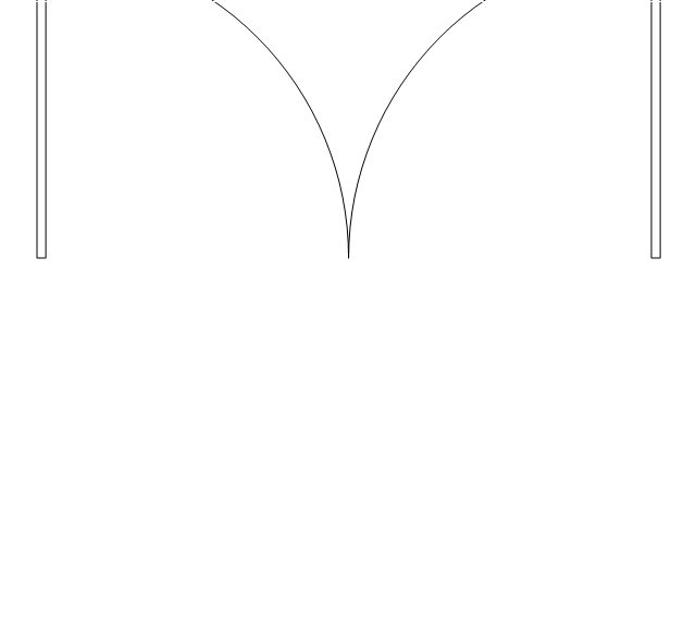
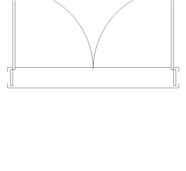
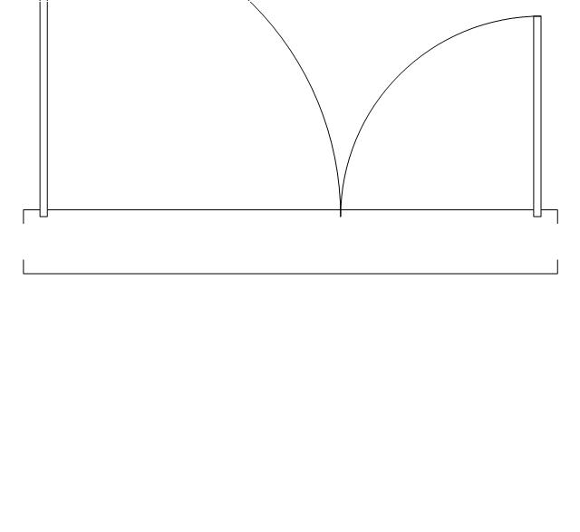
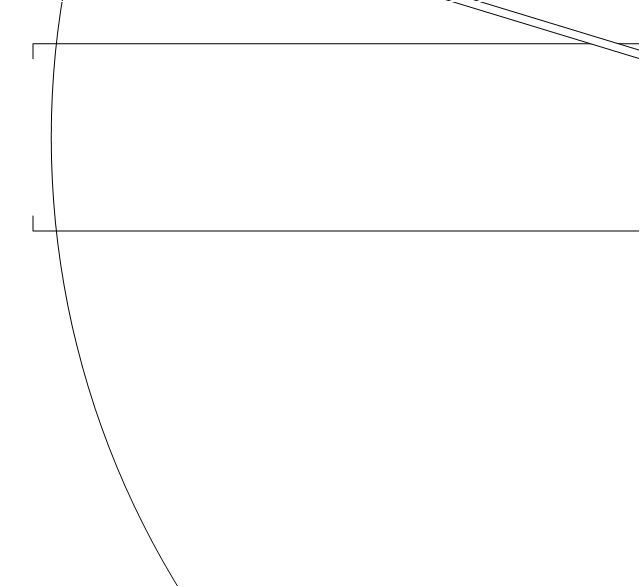
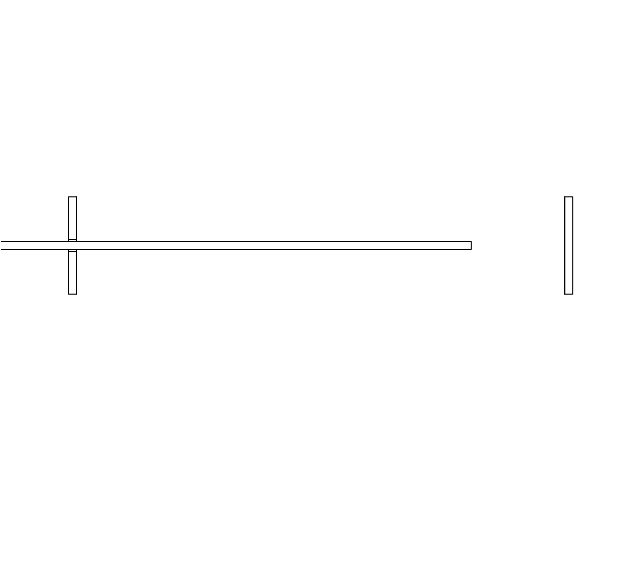
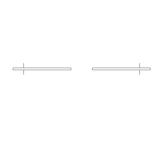
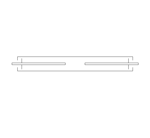
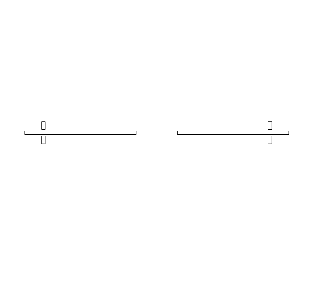
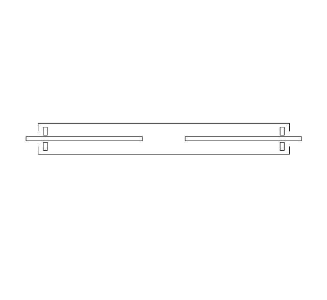
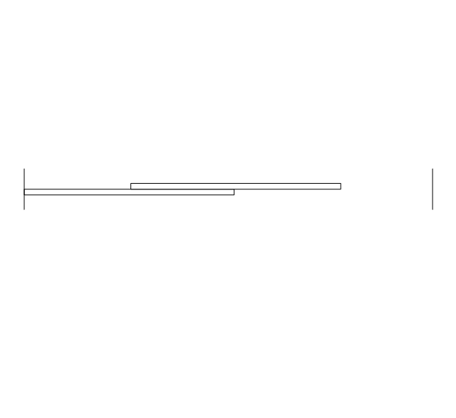
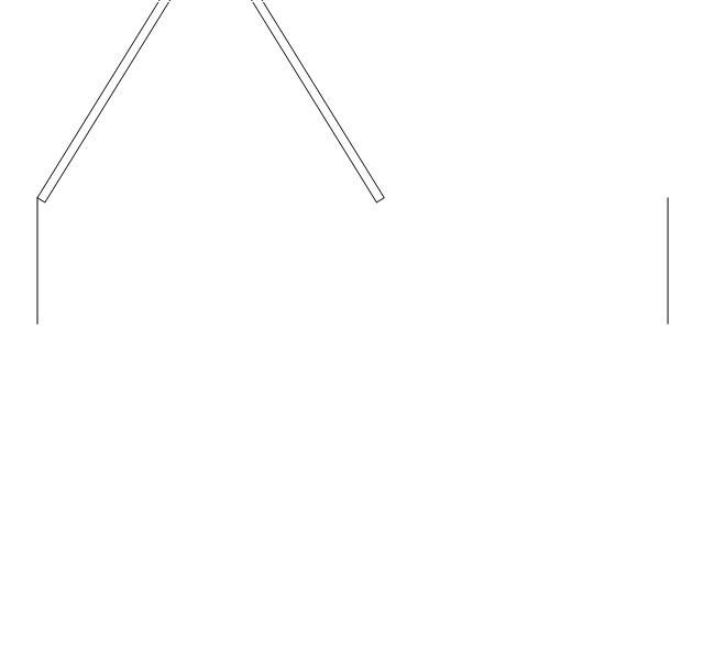
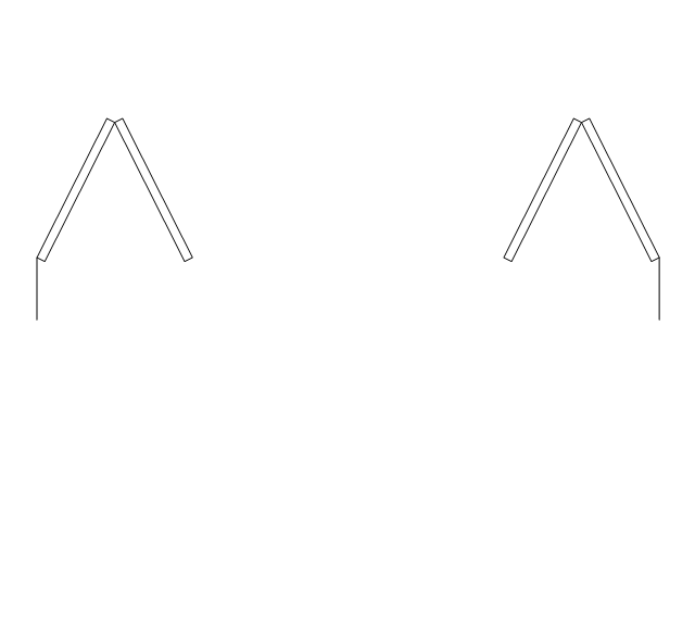
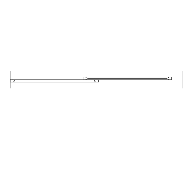
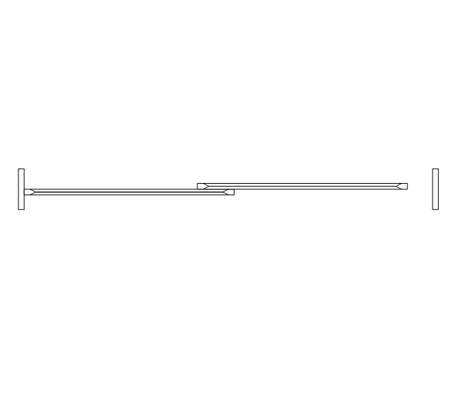
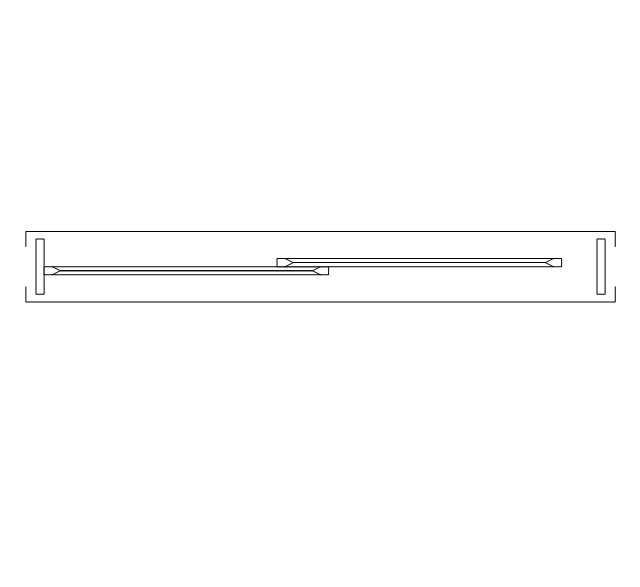
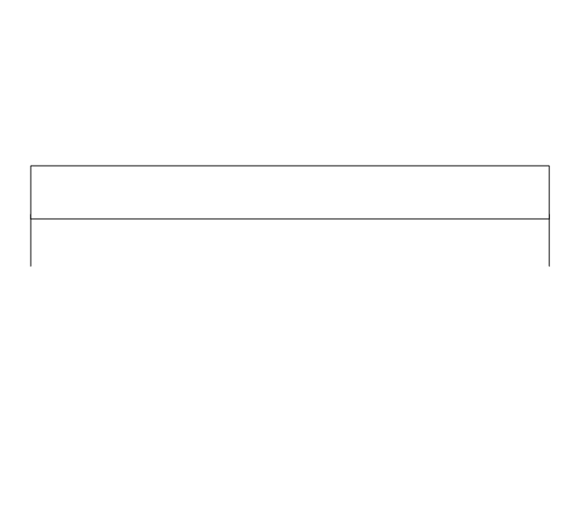
The vector stencils library "Doors" contains 69 shapes of doors. Use it for drawing floor plans in the ConceptDraw PRO diagramming and vector drawing software extended with the Floor Plans solution from the Building Plans area of ConceptDraw Solution Park.
Opening
Door
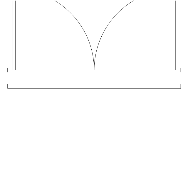
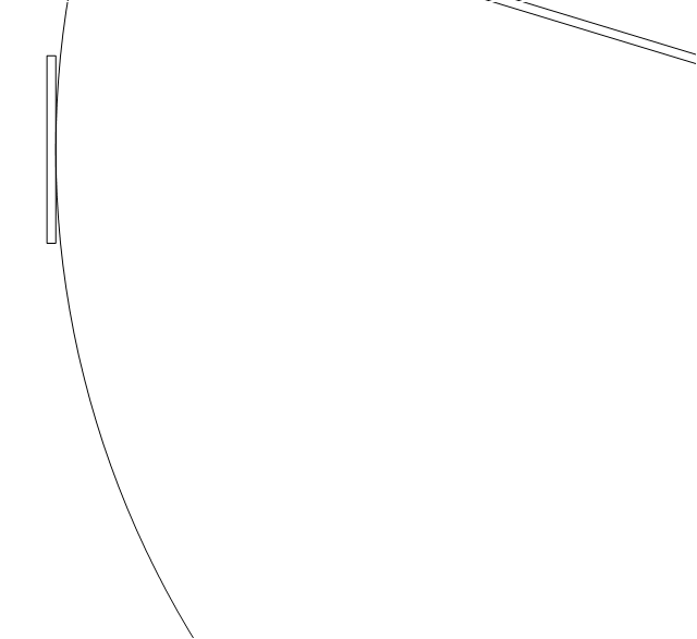
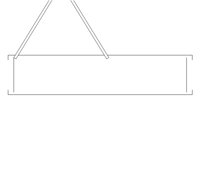
Door, threshold
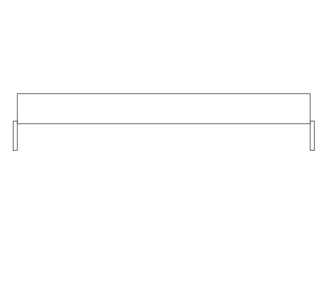
Door, stop
Door, stop, threshold
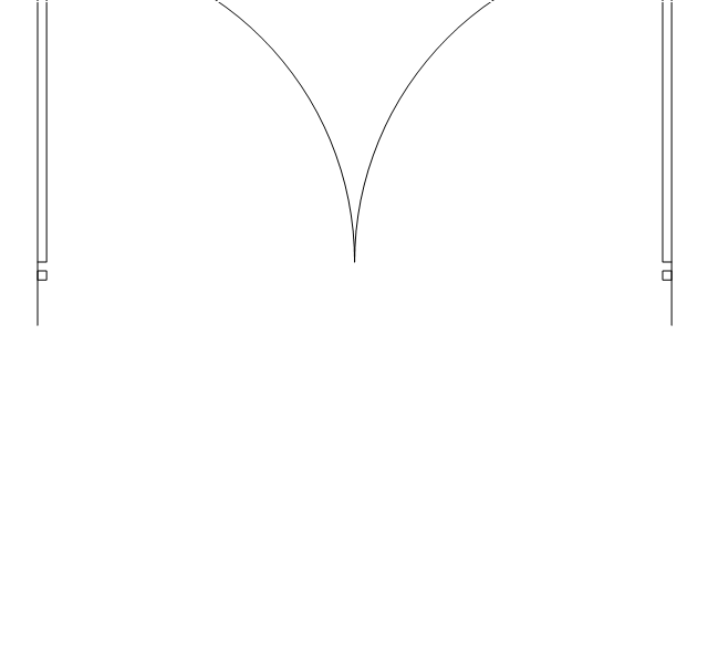
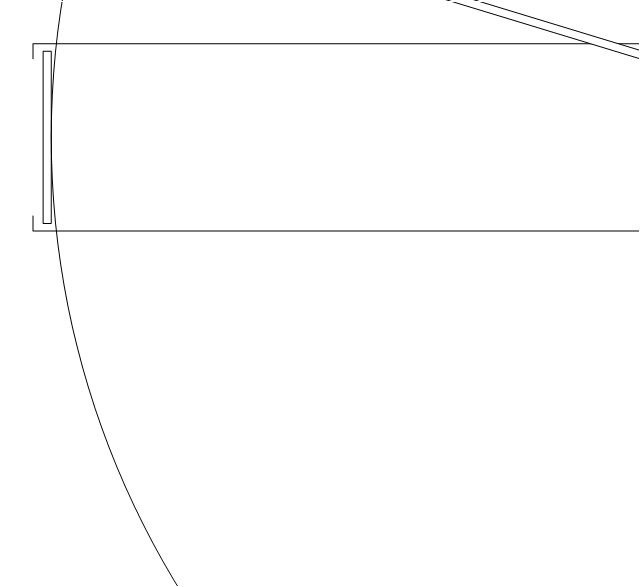
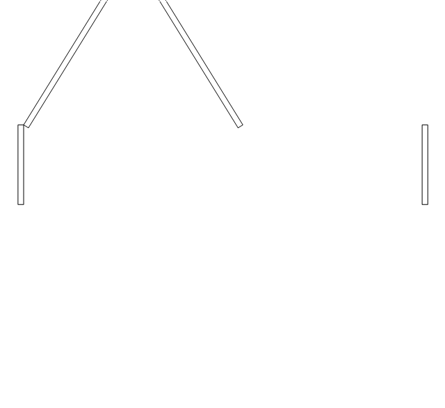
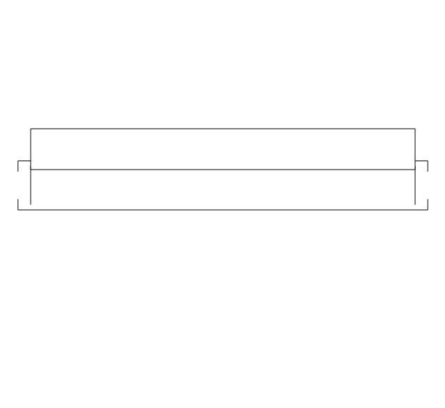
Door, frame
Door, frame, threshold
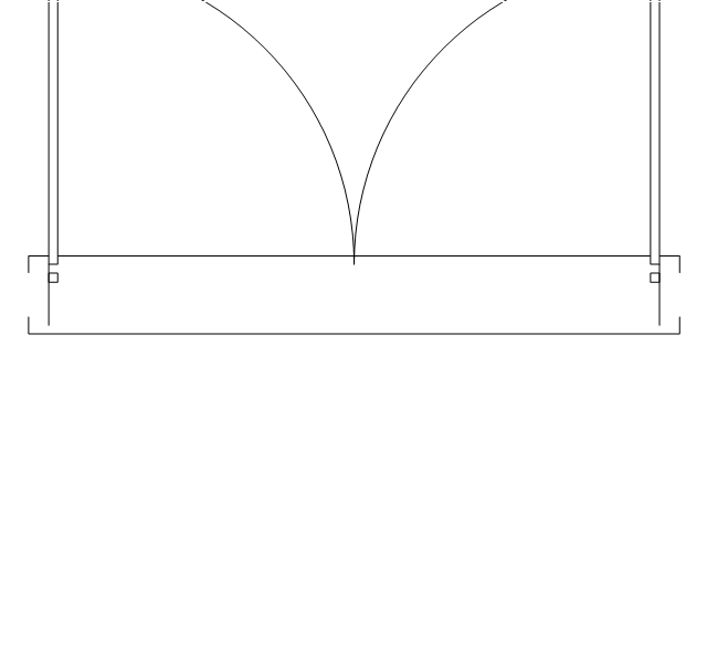
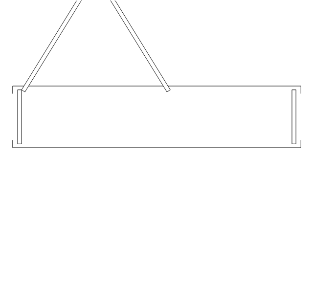
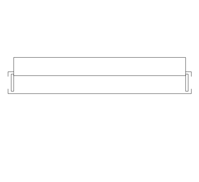
Door, frame, stop

Door, frame, stop, threshold

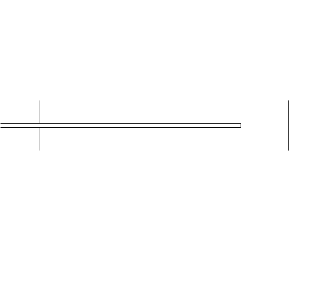
Double hung
Double hung, threshold
Double hung, frame
Double hung, frame, threshold
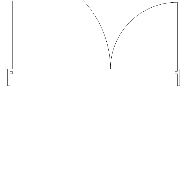
Double door
Double door, threshold
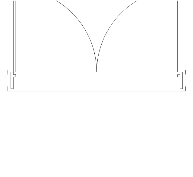
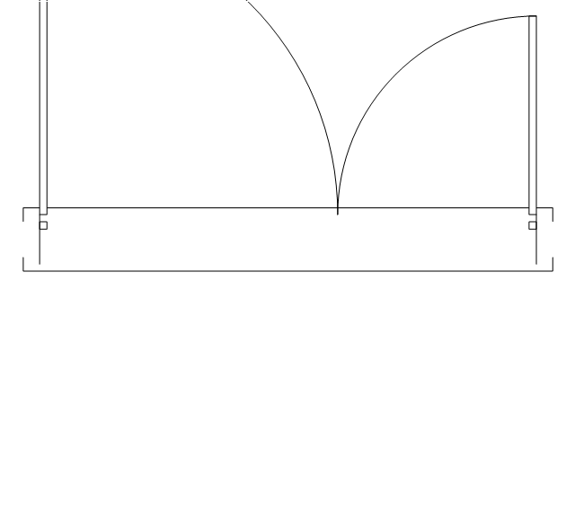
Double door, stop
Double door, stop, threshold
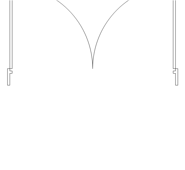
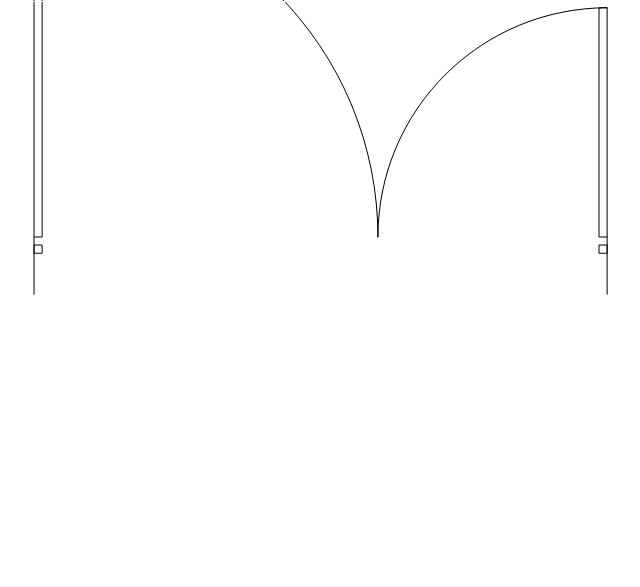
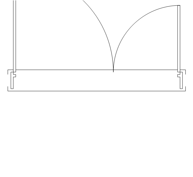
Double door, frame

Double door, frame, threshold
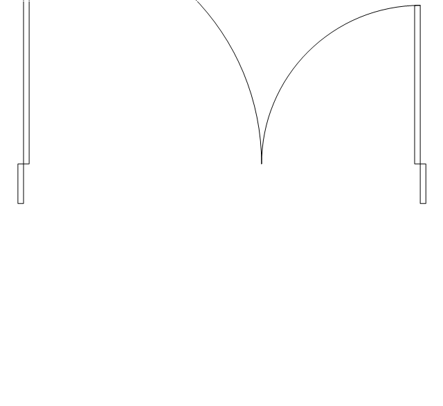
Double door, frame, stop
Double door, frame, stop, threshold
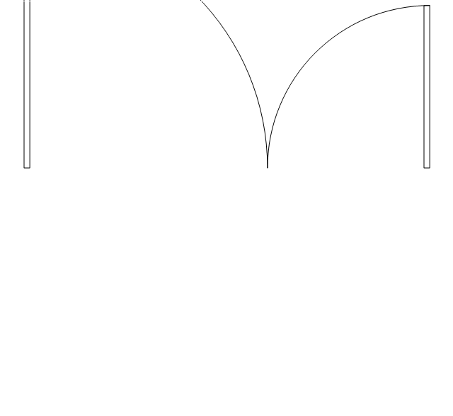
Uneven door
Uneven door, threshold
Uneven door, stop
Uneven door, stop, threshold
Uneven door, frame
Uneven door, frame, threshold

Uneven door, frame, stop
Uneven door, frame, stop, threshold
Opposing door
Opposing door, threshold

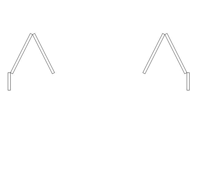
Opposing door, stop
Opposing door, stop, threshold
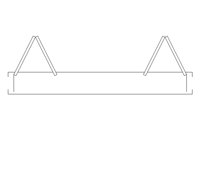
Opposing door, frame

Opposing door, frame, threshold

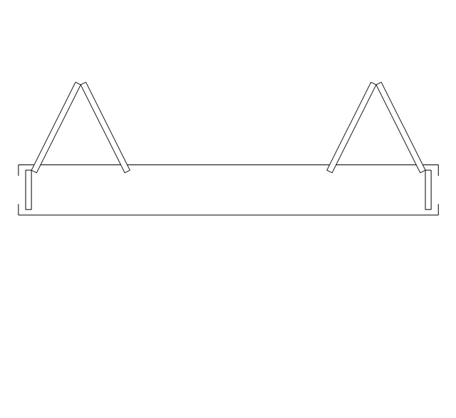
Opposing door, frame, stop
Opposing door, frame, stop, threshold
Revolving door
Revolving door, threshold
Revolving door, frame
Revolving door, frame, threshold
Pocket door
Pocket door, threshold
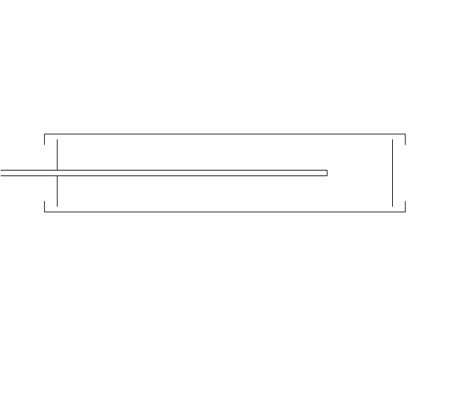
Pocket door, frame
Pocket door, frame, threshold
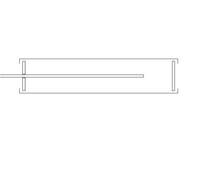
Dbl pocket door
Dbl pocket door, threshold
Dbl pocket door, frame
Dbl pocket door, frame, threshold
By-pass door
By-pass door, threshold

By-pass door, frame

By-pass door, frame, threshold

Bi-fold door
Bi-fold door, threshold
Bi-fold door, frame
Bi-fold door, frame, threshold
Double bi-fold door
Double bi-fold door, threshold
Double bi-fold door, frame
Double bi-fold door, frame, threshold
Sliding glass
Sliding glass, threshold
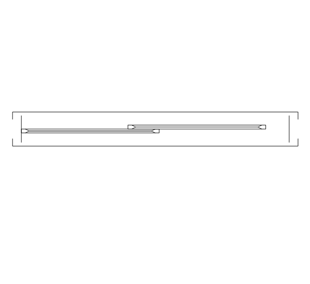
Sliding glass, frame
Sliding glass, frame, threshold
Overhead door
Overhead door, threshold
Overhead door, frame
Overhead door, frame, threshold
Interior Design Shipping and Receiving - Design Elements

The vector stencils library "Shipping and receiving" contains 18 symbols of industrial shipping and receiving equipment.
Use the design elements library "Shipping and receiving" to draw factory warehouse equipment layout plans, floor plans of shipping and receiving centers with equipment for hauling, transporting, and distributing manufactured goods, freight, cargo, and stock from plants and industrial facilities using the ConceptDraw PRO diagramming and vector drawing software.
"Freight transport, or shipping, is a key in the value chain in manufacturing.
While all modes of transport are used for cargo transport, there is high differentiation between the nature of the cargo transport, in which mode is chosen.
Logistics refers to the entire process of transferring products from producer to consumer, including storage, transport, transshipment, warehousing, material-handling and packaging, with associated exchange of information.
Containerization, with the standardization of ISO containers on all vehicles and at all ports, has revolutionized international and domestic trade, offering huge reduction in transshipment costs. Traditionally, all cargo had to be manually loaded and unloaded into the haul of any ship or car; containerization allows for automated handling and transfer between modes, and the standardized sizes allow for gains in economy of scale in vehicle operation." [Transport. Freight.
Wikipedia]
This shapes library "Shipping and receiving" is included in the Plant Layout Plans solution from the Building Plans area of ConceptDraw Solution Park.
Shipping and receiving symbols

Home Electrical Plan

Electrical Symbols — Thermo

How To Create CCTV Network Diagram

Electrical Symbols — VHF UHF SHF

Electrical Symbols — Resistors

- How To use Appliances Symbols for Building Plan | Design ...
- Architectural Symbols For Revolving Door
- Doors Symbols
- Conventional Symbols For Folding Door
- Design elements - Doors and windows | How To use Appliances ...
- Door Symbols
- House Plan Symbols Of Sliding Door Drawing Plan
- Architectural Symbols Of Revolving Door
- Design elements - Doors and windows | Electrical Drawing Software ...
- Design elements - Alarm and access control | Electrical Symbols ...
- House Plan Door Windows Symbols
- Design elements - Doors and windows | ConceptDraw PRO The ...
- Casement Door Symbols
- Architectural Symbols Casement Windows
- Basic Engineering Civil Home Door Window Symbols
- Window And Door Symbols
- Design elements - Doors and windows
- Symbols For Doors And Windows
- Symbol Of Door And Windows In Drawing Of Building
- Symbols Of Door Window Stove Couch Fridge Bed Toilet Shower ...