Electrical Symbols, Electrical Schematic Symbols

Electrical Symbols, Electrical Diagram Symbols

Swim Lane Flowchart Symbols

The vector stencils library "Resistors" contains 14 element symbols of resistors for drawing electronic schematics, circuit diagrams and electrical drawings.
"A resistor is a passive two-terminal electrical component that implements electrical resistance as a circuit element. Resistors act to reduce current flow, and, at the same time, act to lower voltage levels within circuits. Resistors may have fixed resistances or variable resistances, such as those found in thermistors, varistors, trimmers, photoresistors and potentiometers.
The current through a resistor is in direct proportion to the voltage across the resistor's terminals. This relationship is represented by Ohm's law ...
Resistors are common elements of electrical networks and electronic circuits and are ubiquitous in electronic equipment. Practical resistors can be composed of various compounds and films, as well as resistance wires (wire made of a high-resistivity alloy, such as nickel-chrome). Resistors are also implemented within integrated circuits, particularly analog devices, and can also be integrated into hybrid and printed circuits." [Resistor. Wikipedia]
The shapes example "Design elements - Resistors" was drawn using the ConceptDraw PRO diagramming and vector drawing software extended with the Electrical Engineering solution from the Engineering area of ConceptDraw Solution Park.
Resistor symbols

Electrical Drawing Software and Electrical Symbols

Electrical Diagram

Circuits and Logic Diagram Software

How To use Electrical and Telecom Plan Software


Electrical Diagram Software


Electrical Symbols — Composite Assemblies

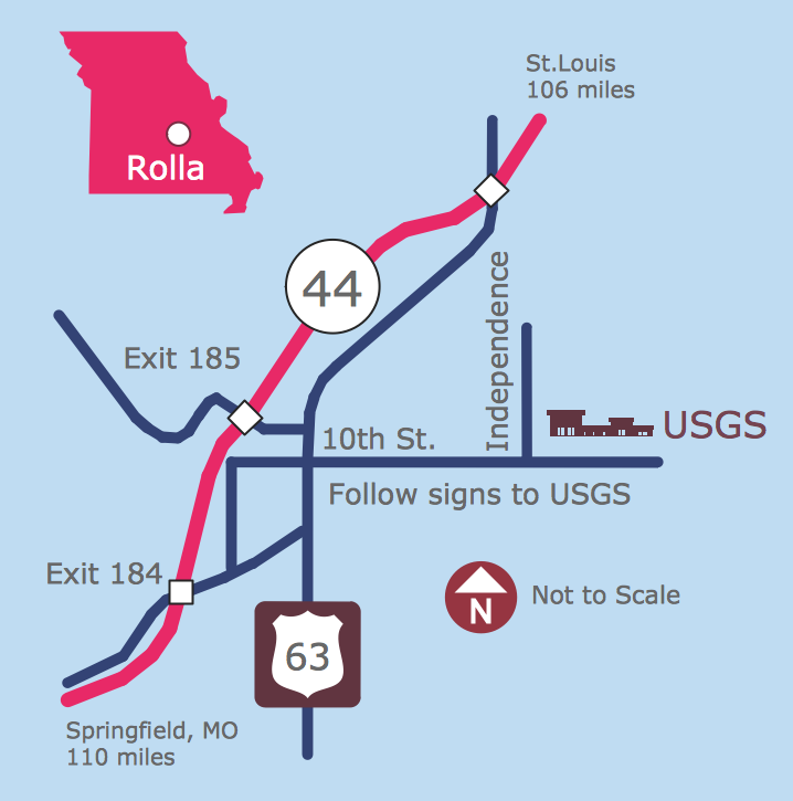
Maps and Directions
Process Flow Diagram

The vector stencils library "Logic gate diagram" contains 17 element symbols for drawing the logic gate diagrams.
"To build a functionally complete logic system, relays, valves (vacuum tubes), or transistors can be used. The simplest family of logic gates using bipolar transistors is called resistor-transistor logic (RTL). Unlike simple diode logic gates (which do not have a gain element), RTL gates can be cascaded indefinitely to produce more complex logic functions. RTL gates were used in early integrated circuits. For higher speed and better density, the resistors used in RTL were replaced by diodes resulting in diode-transistor logic (DTL). Transistor-transistor logic (TTL) then supplanted DTL. As integrated circuits became more complex, bipolar transistors were replaced with smaller field-effect transistors (MOSFETs); see PMOS and NMOS. To reduce power consumption still further, most contemporary chip implementations of digital systems now use CMOS logic. CMOS uses complementary (both n-channel and p-channel) MOSFET devices to achieve a high speed with low power dissipation." [Logic gate. Wikipedia]
The symbols example "Design elements - Logic gate diagram" was drawn using the ConceptDraw PRO diagramming and vector drawing software extended with the Electrical Engineering solution from the Engineering area of ConceptDraw Solution Park.
Logic gate symbols

Technical Drawing Software

Mechanical Design Software

- Draw Symbols Of Different Compound Used In Electric Circuit
- Different Symbols Of Resistor
- Resistor Symbol
- Example Of Circuit Symbol For Fixed Resistor
- Electrical Symbols , Electrical Diagram Symbols | Electrical Symbols ...
- Electrical Symbols — Resistors | Design elements - Resistors | Local ...
- Resistors Examples And Symbols
- Electrical Symbols — Resistors | Design elements - Astronomical ...
- Electrical Symbols , Electrical Diagram Symbols | Electrical Symbols ...
- Electrical Symbols — Thermo | Electrical Symbols — Resistors ...
- Electrical Symbols — Composite Assemblies | Electrical Symbols ...
- Electrical Symbols — Resistors | Design elements - Resistors ...
- Electrical Symbols — Resistors | Electrical Symbols — MOSFET ...
- Mechanical Drawing Symbols | Building Drawing Software for ...
- Design elements - Resistors | Electrical Drawing Software and ...
- Electrical Drawing Software and Electrical Symbols | Design ...
- Electrical Symbols — Thermo | Electrical Symbols — Resistors ...
- Electrical Symbols — Thermo | Electrical Symbols — Resistors ...
- Mechanical Drawing Symbols | Mechanical Engineering | Retract ...
- Design elements - Resistors | Design elements - Electrical circuits ...