Process Flow Diagram Symbols

 Chemical and Process Engineering
This chemical engineering solution extends ConceptDraw PRO v.9.5 (or later) with process flow diagram symbols, samples, process diagrams templates and libraries of design elements for creating process and instrumentation diagrams, block flow diagrams (BFD
Process Flowchart


Physics Diagrams

Design Element: Basic Network for Network Diagrams
.png "Network Diagramming Tools, Design Elements - Basic Network (Win Mac)")

Network Diagramming Software for Design Computer and Network Diagrams
_Win_Mac.png "Network Diagramming Software, Design Elements — Computer and Network (Windows, Macintosh)")
Electrical Symbols, Electrical Diagram Symbols

HelpDesk
How to Draw a Chemical Process Flow Diagram

Basic Flowchart Symbols and Meaning


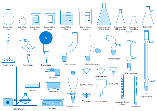
The vector stencils library "Laboratory equipment" contains 31 clipart icons of chemical laboratory equipment and labware for drawing part assembly and mounting schemes of glassware apparatus in chemical experiment diagrams and illustrations.
"Laboratory glassware refers to a variety of equipment, traditionally made of glass, used for scientific experiments and other work in science, especially in chemistry and biology laboratories. ...
Glass use in laboratory applications is not as commonplace as it once was because of cheaper, less breakable, plasticware; however, certain applications still require glassware because glass is relatively inert, transparent, heat-resistant, and easy to customize. The type of glass used is dependent on the application. Borosilicate glass, which is commonly used in reagent bottles, can withstand thermal stress. Quartz glass, which is common in cuvettes, can withstand high temperatures and is transparent in certain parts of the electromagnetic spectrum. Darkened brown or amber (actinic) glass, which is common in dark storage bottles, can block ultraviolet and infrared radiation. Heavy-wall glass, which is common in glass pressure reactors, can withstand pressurized applications." [Laboratory glassware. Wikipedia]
The chemical symbols example "Design elements - Laboratory equipment" was created using the ConceptDraw PRO software extended with the Chemistry solution from the Science and Education area of ConceptDraw Solution Park.
Labware
Local area network (LAN). Computer and Network Examples
. Computer and Network Examples")
Chemistry Drawing Software

Personal area (PAN) networks. Computer and Network Examples
 networks. Computer and Network Examples")
Organic Chemistry Symbols

Process Engineering

- List The Uses And Diagram Of Chemistry Laboratory Apparatus
- Chemistry Apparatus With Their Diagrams And Uses
- 20 Chemical Apparatus
- Chemistry Laboratory Apparatus And Their Uses Wikipedia
- Physics Diagrams | List Of Physics Apparatus And Their Uses
- 50 Common Laboratory Apparatus Their Uses
- Drawing Of Chemistry Apparatus And Their Uses
- Common Chemistry Apparatus And Their Uses
- Laboratory Apparatus And Their Uses With Pictures Wikipedia
- List Of Laboratory Apparatus And Their Uses With Pictures
- Physics Diagrams | List Of Physics Laboratory Apparatus And Their ...
- 80 Laboratory Apparatus With Diagram And Their Uses
- Diagram Of 80 Laboratory Apparatus And Their Uses
- Diagram Of 20 Equipment In The Lab And Their Name And Uses
- Electrical Symbols, Electrical Diagram Symbols | 20 Apparatus Their ...
- Chemistry Apparatus Diagram And Their Uses
- Physics Diagrams | Physics Laboratory Apparatus And Their Uses Pdf
- Diagram 50 Glasswares Used In The Chemistry Lab And Their Uses
- Some Chemistry Apparatus And The Uses With Diagram
- Chemistry Laboratory Diagram And Their Uses