Network Diagram Examples


Network Diagramming with ConceptDraw DIAGRAM

Draw Network Diagram based on Templates and Examples

Network Diagram Software

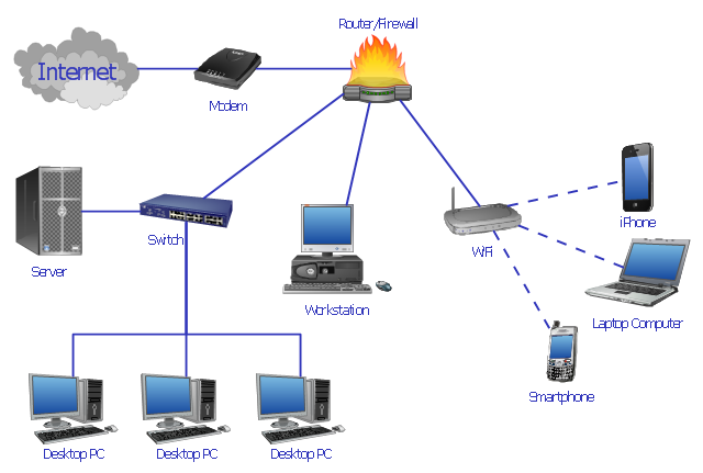
Basic Network Diagram

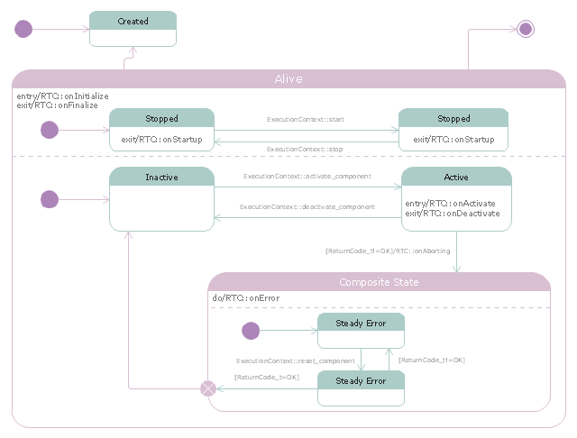
"RT-middleware (Robotics Technology Middleware) is a common platform standards for Robots based on the distributed object technology. RT-middleware supports the construction of various networked robotic systems by the integration of various network enabled robotic elements called RT-Components. The specification standard of the RT-component is discussed / defined by the Object Management Group (OMG). ...
In the RT-middleware, robotics elements, such as actuators, are regarded as RT-components, and the whole robotic system is constructed by connecting those RT-components. This distributed architecture helps developers to re-use the robotic elements, and boosts the reliability of the robotic system.
Each RT-component has port as an endpoint for communicating other RT-components. Every port has its type and the ports which have the same type can be connected each other.
RT-components also has its state, so the RT-components behaves as state machines. The states that RT-components can have are CREATED, INACTIVE, ACTIVE, and ERROR, and the states and behaviors are controlled by the execution-context. If developers want to change the behavior of their RT-components, the execution-context can be replaced at run-time." [RT middleware. Wikipedia]
The UML state machine diagram example "State transitions of RT-component" was created using the ConceptDraw PRO diagramming and vector drawing software extended with the Rapid UML solution from the Software Development area of ConceptDraw Solution Park.
UML state machine diagram
Network Hubs

This telecom diagram sample illustrates the call shop solution. It was designed on the base of the Wikimedia Commons file: Call shops.jpg.
[commons.wikimedia.org/ wiki/ File:Call_ shops.jpg]
This file is licensed under the Creative Commons Attribution-Share Alike 3.0 Unported license. [creativecommons.org/ licenses/ by-sa/ 3.0/ deed.en]
"A call shop is a business providing on-site access to telephones for long-distance calling in countries without widespread home long-distance service. Calls may be prepaid or postpaid." [Call shop. Wikipedia]
The telecommunication diagram example "Call shop solution" was created using the ConceptDraw PRO diagramming and vector drawing software extended with the Computers and Communications solution from the Illustration area of ConceptDraw Solution Park.
Telecom diagram

"Network planning and design is an iterative process, encompassing topological design, network-synthesis, and network-realization, and is aimed at ensuring that a new telecommunications network or service meets the needs of the subscriber and operator. Network planning process involves three main steps: 1) Topological design: This stage involves determining where to place the components and how to connect them. 2) Network-synthesis: This stage involves determining the size of the components used, subject to performance criteria such as the Grade of Service (GoS). 3) Network realization: This stage involves determining how to meet capacity requirements, and ensure reliability within the network." [Network planning and design. Wikipedia]
This computer network system design diagram example was created using the ConceptDraw PRO diagramming and vector drawing software extended with the Computer and Networks solution from the Computer and Networks area of ConceptDraw Solution Park.
This computer network system design diagram example was created using the ConceptDraw PRO diagramming and vector drawing software extended with the Computer and Networks solution from the Computer and Networks area of ConceptDraw Solution Park.
Network system design
"Network topology is the arrangement of the various elements (links, nodes, etc.) of a computer network. Essentially, it is the topological structure of a network, and may be depicted physically or logically. Physical topology refers to the placement of the network's various components, including device location and cable installation, while logical topology shows how data flows within a network, regardless of its physical design. Distances between nodes, physical interconnections, transmission rates, and/ or signal types may differ between two networks, yet their topologies may be identical. The study of network topology recognizes eight basic topologies: Point-to-point, Bus, Star, Ring or circular, Mesh, Tree, Hybrid, Daisy chain." [Network topology. Wikipedia]
The computer network topologies diagram example was created using the ConceptDraw PRO diagramming and vector drawing software extended with the Computer and Networks solution from the Computer and Networks area of ConceptDraw Solution Park.
The computer network topologies diagram example was created using the ConceptDraw PRO diagramming and vector drawing software extended with the Computer and Networks solution from the Computer and Networks area of ConceptDraw Solution Park.
Network topologies

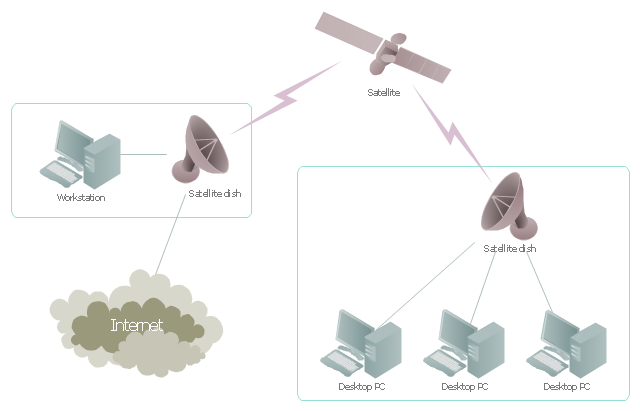
"Satellite Internet access is Internet access provided through communications satellites. ...
Satellite Internet generally relies on three primary components: a satellite in geostationary orbit (sometimes referred to as a geosynchronous Earth orbit, or GEO), a number of ground stations known as gateways that relay Internet data to and from the satellite via radio waves (microwave), and a VSAT (very-small-aperture terminal) dish antenna with a transceiver, located at the subscriber's premises. Other components of a satellite Internet system include a modem at the user end which links the user's network with the transceiver, and a centralized network operations center (NOC) for monitoring the entire system. Working in concert with a broadband gateway, the satellite operates a Star network topology where all network communication passes through the network's hub processor, which is at the center of the star. With this configuration, the number of remote VSATs that can be connected to the hub is virtually limitless." [Satellite Internet access. Wikipedia]
This satellite telecom network diagram example was created using the ConceptDraw PRO diagramming and vector drawing software extended with the Telecommunication Network Diagrams solution from the Computer and Networks area of ConceptDraw Solution Park.
Satellite telecom network diagram
"Deployment diagram shows execution architecture of systems that represent the assignment (deployment) of software artifacts to deployment targets (usually nodes).
Nodes represent either hardware devices or software execution environments. They could be connected through communication paths to create network systems of arbitrary complexity. Artifacts represent concrete elements in the physical world that are the result of a development process and are deployed on nodes.
Note, that components were directly deployed to nodes in UML 1.x deployment diagrams. In UML 2.x artifacts are deployed to nodes, and artifacts could manifest (implement) components. So components are now deployed to nodes indirectly through artifacts." [uml-diagrams.org/ deployment-diagrams.html]
The template "UML deployment diagram" for the ConceptDraw PRO diagramming and vector drawing software is included in the Rapid UML solution from the Software Development area of ConceptDraw Solution Park.
www.conceptdraw.com/ solution-park/ software-uml
UML deployment diagram

 Bubble Diagrams
Bubble diagrams have enjoyed great success in software engineering, architecture, economics, medicine, landscape design, scientific and educational process, for ideas organization during brainstorming, for making business illustrations, presentations, planning, design, and strategy development. They are popular because of their simplicity and their powerful visual communication attributes.
- UML Component Diagram | Draw Network Diagram based on ...
- UML Deployment Diagram | Design Element: Basic Network for ...
- Wiring Diagrams with ConceptDraw PRO | Home area network (HAN)
- How To use Switches in Network Diagram | Network Diagramming ...
- UML Diagram | ConceptDraw PRO Network Diagram Tool | Process ...
- Local area network (LAN) diargam | Network Diagram Examples ...
- ConceptDraw PRO Network Diagram Tool | Wiring Diagrams with ...
- Network diagrams with ConceptDraw PRO | ConceptDraw PRO ...
- UML Component Diagram Example - Online Shopping ...
- Wiring Diagrams with ConceptDraw PRO | Basic Network Diagram ...
- Home area network (HAN) wiring diagram | Network diagrams with ...
- Network Diagram Examples | Bus network topology diagram | Basic ...
- Network Diagram Software Home Area Network | Local area ...
- Design Element: Rack Diagram for Network Diagrams | How to Draw ...
- Computer network system design diagram | How to Draw a ...
- Engineering | Wiring Diagrams with ConceptDraw PRO | Applications |
- UML Class Diagram Example - Social Networking Site | Data ...
- Computer network system design diagram | Network Diagramming ...
- Communication network diagram | Computers and Communications ...
- Logical network diagram | Diagramming tool - Amazon Web ...