HelpDesk
How to Create a Wireless Network Diagram Using ConceptDraw Solutions

 Computer and Networks Area
The solutions from Computer and Networks Area of ConceptDraw Solution Park collect samples, templates and vector stencils libraries for drawing computer and network diagrams, schemes and technical drawings.
"A server is a system (software and suitable computer hardware) that responds to requests across a computer network to provide, or help to provide, a network service. Servers can be run on a dedicated computer, which is also often referred to as "the server", but many networked computers are capable of hosting servers. In many cases, a computer can provide several services and have several servers running.
Servers operate within a client-server architecture. Servers are computer programs running to serve the requests of other programs, the clients. Thus, the server performs some tasks on behalf of clients. The clients typically connect to the server through the network but may run on the same computer. In the context of Internet Protocol (IP) networking, a server is a program that operates as a socket listener.
Servers often provide essential services across a network, either to private users inside a large organization or to public users via the Internet. Typical computing servers are database server, file server, mail server, print server, web server, gaming server, application server, or some other kind of server.
Numerous systems use this client / server networking model including Web sites and email services. An alternative model, peer-to-peer networking enables all computers to act as either a server or client as needed." [Server (computing). Wikipedia]
The UML component diagram example "Start server" was created using the ConceptDraw PRO diagramming and vector drawing software extended with the Rapid UML solution from the Software Development area of ConceptDraw Solution Park.
UML component diagram

"Satellite Internet access is Internet access provided through communications satellites. ...
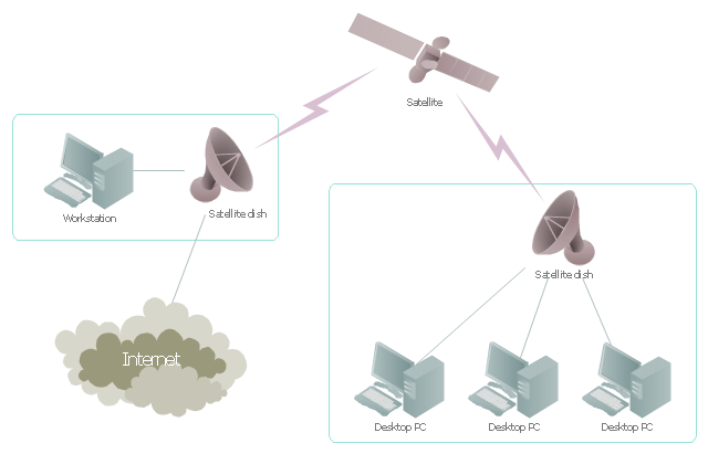
Satellite Internet generally relies on three primary components: a satellite in geostationary orbit (sometimes referred to as a geosynchronous Earth orbit, or GEO), a number of ground stations known as gateways that relay Internet data to and from the satellite via radio waves (microwave), and a VSAT (very-small-aperture terminal) dish antenna with a transceiver, located at the subscriber's premises. Other components of a satellite Internet system include a modem at the user end which links the user's network with the transceiver, and a centralized network operations center (NOC) for monitoring the entire system. Working in concert with a broadband gateway, the satellite operates a Star network topology where all network communication passes through the network's hub processor, which is at the center of the star. With this configuration, the number of remote VSATs that can be connected to the hub is virtually limitless." [Satellite Internet access. Wikipedia]
This satellite telecom network diagram example was created using the ConceptDraw PRO diagramming and vector drawing software extended with the Telecommunication Network Diagrams solution from the Computer and Networks area of ConceptDraw Solution Park.
Satellite telecom network diagram
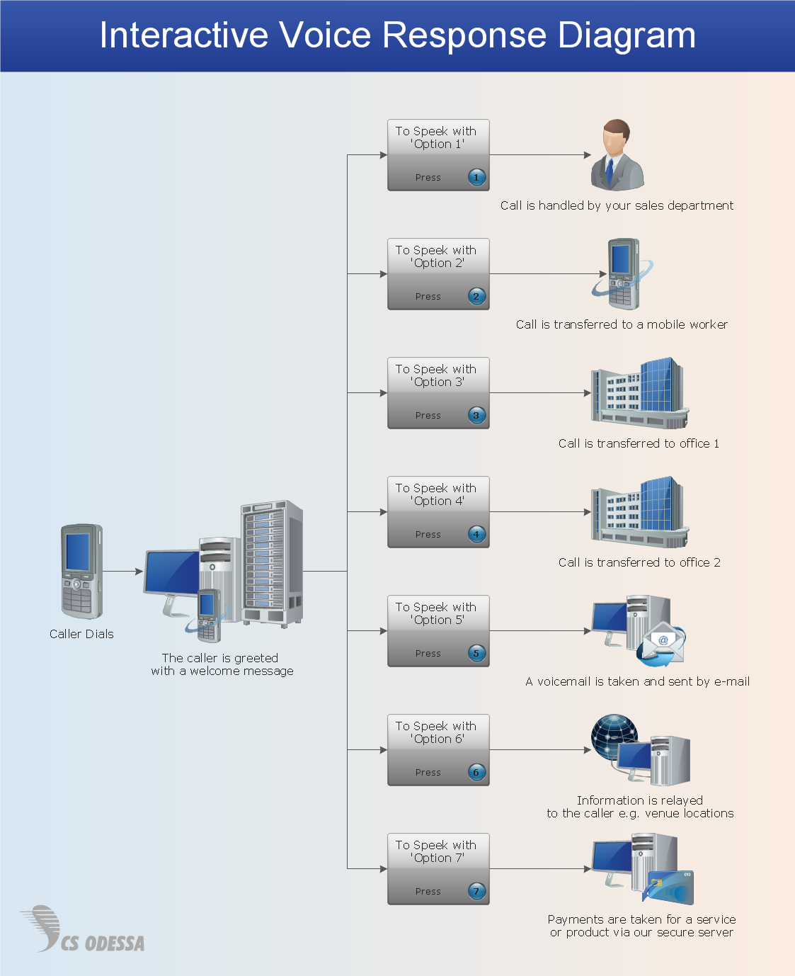
 Interactive Voice Response Diagrams
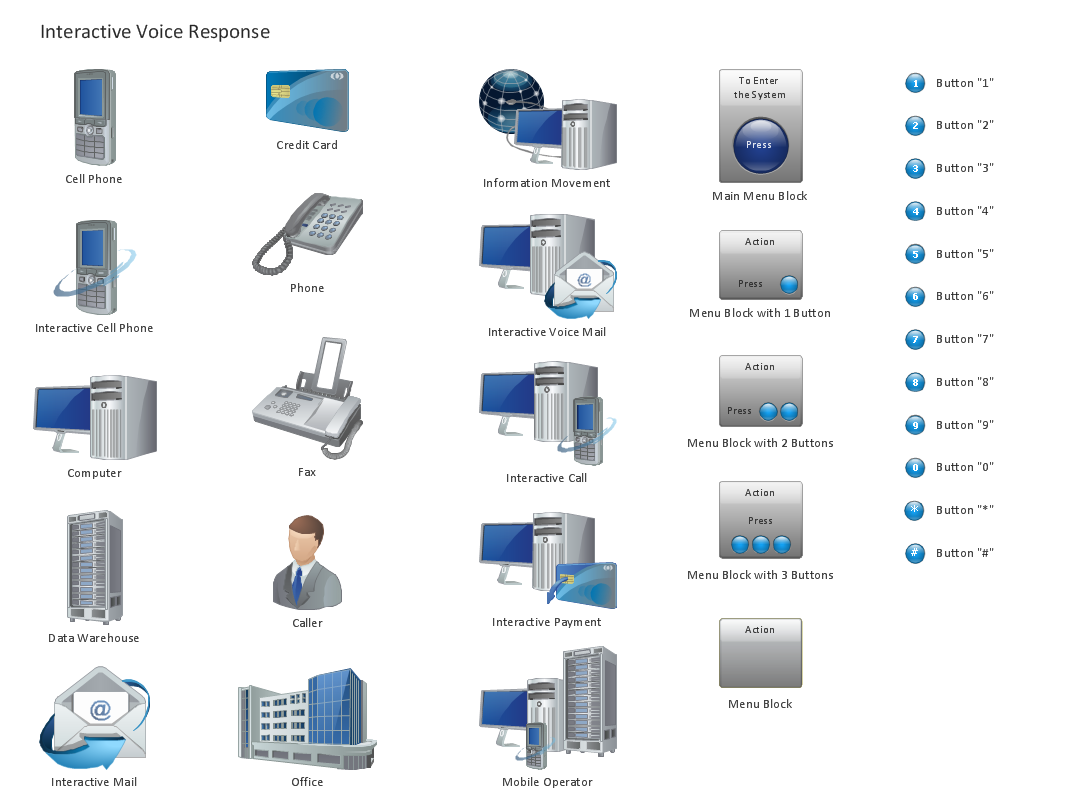
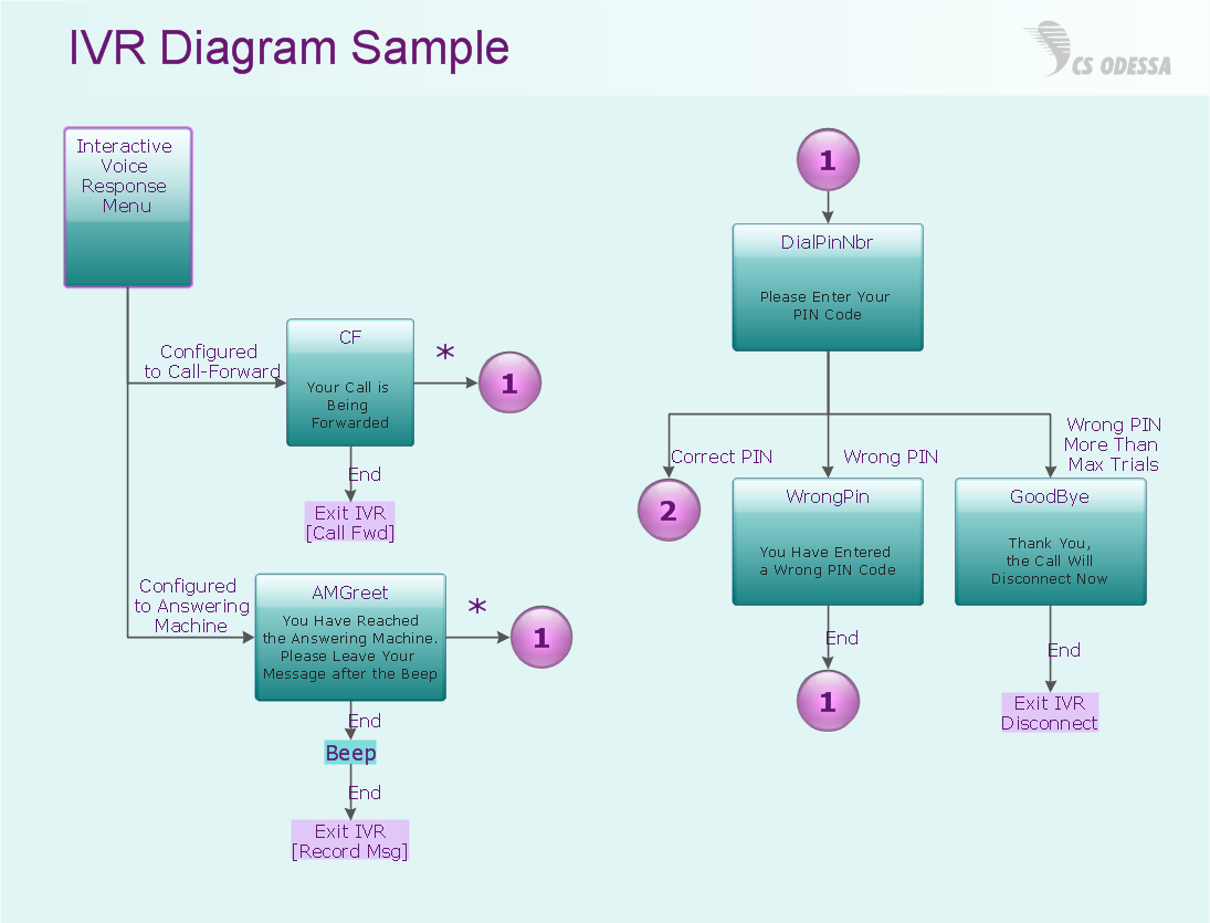
Interactive Voice Response Diagrams solution extends ConceptDraw DIAGRAM software with samples, templates and libraries of ready-to-use vector stencils that help create Interactive Voice Response (IVR) diagrams illustrating in details a work of interactive voice response system, the IVR system’s logical and physical structure, Voice-over-Internet Protocol (VoIP) diagrams, and Action VoIP diagrams with representing voice actions on them, to visualize how the computers interact with callers through voice recognition and dual-tone multi-frequency signaling (DTMF) keypad inputs.
Network Diagramming Software for Design IVR Network Diagrams
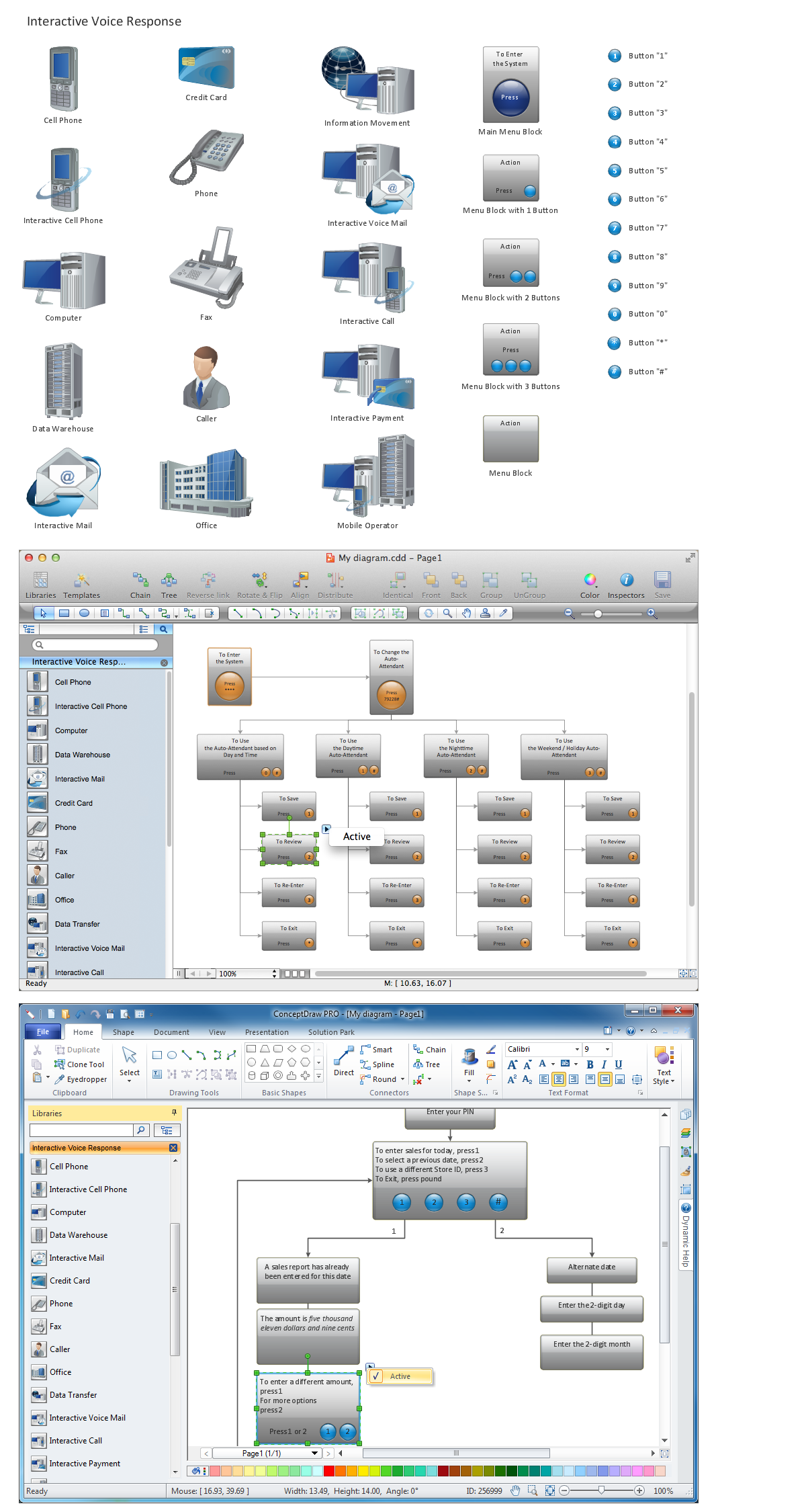

Design Element: IVR for Network Diagrams
- Computer Network Diagrams | ConceptDraw PRO Network Diagram ...
- Call center network diagram | Computers and network isometric ...
- Wireless Networks | How to Create a Wireless Network Diagram ...
- Computer Network Diagram From Interet To Pc
- Telecommunication Network Diagrams | How to Create a ...
- Diagram Vsat Computer Network
- Satellite telecom network diagram | Local area network ( LAN ...
- Cisco Network Diagrams | Computer Network Diagrams | PM ...
- How To Convert a Computer Network Diagram to Adobe PDF Using ...
- How to Draw a Computer Network Diagrams | Computer and ...
- Remote Computer Monitoring System For Component Diagram
- How to Draw a Computer Network Diagrams | Computer and ...
- How to Create a Wireless Network Diagram | How to Add a Wireless ...
- How to Draw a Computer Network Diagrams
- Venn diagram - Internet marketing professions | Internet Connectivity ...
- How to Operate a Multiple Main Idea on Your Mind Map | How to ...
- Home area networks (HAN). Computer and Network Examples ...
- Telecommunication Network Diagrams | How To Create a MS Visio ...
- Call center network diagram | Trouble ticket system - BPMN 2.0 ...