This computer security diagram example was designed on the base of the Wikimedia Commons file: Firewall.png.
[commons.wikimedia.org/ wiki/ File:Firewall.png]
This file is licensed under the Creative Commons Attribution-Share Alike 3.0 Unported license. [creativecommons.org/ licenses/ by-sa/ 3.0/ deed.en]
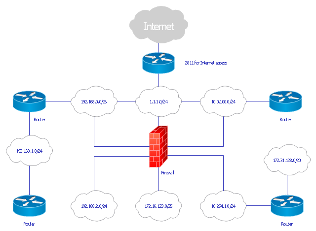
"In computing, a firewall is a network security system that monitors and controls the incoming and outgoing network traffic based on predetermined security rules. A firewall typically establishes a barrier between a trusted, secure internal network and another outside network, such as the Internet, that is assumed to not be secure or trusted. Firewalls are often categorized as either network firewalls or host-based firewalls. Network firewalls are a software appliance running on general purpose hardware or hardware-based firewall computer appliances that filter traffic between two or more networks. Host-based firewalls provide a layer of software on one host that controls network traffic in and out of that single machine. Firewall appliances may also offer other functionality to the internal network they protect such as acting as a DHCP or VPN server for that network." [Firewall (computing). Wikipedia]
The cybersecurity diagram example "Firewall between LAN and WAN" was created using the ConceprDraw PRO software extended with the Network Security Diagrams solution from the Computer and Neworks area of ConceptDraw Solution Park.
[commons.wikimedia.org/ wiki/ File:Firewall.png]
This file is licensed under the Creative Commons Attribution-Share Alike 3.0 Unported license. [creativecommons.org/ licenses/ by-sa/ 3.0/ deed.en]
"In computing, a firewall is a network security system that monitors and controls the incoming and outgoing network traffic based on predetermined security rules. A firewall typically establishes a barrier between a trusted, secure internal network and another outside network, such as the Internet, that is assumed to not be secure or trusted. Firewalls are often categorized as either network firewalls or host-based firewalls. Network firewalls are a software appliance running on general purpose hardware or hardware-based firewall computer appliances that filter traffic between two or more networks. Host-based firewalls provide a layer of software on one host that controls network traffic in and out of that single machine. Firewall appliances may also offer other functionality to the internal network they protect such as acting as a DHCP or VPN server for that network." [Firewall (computing). Wikipedia]
The cybersecurity diagram example "Firewall between LAN and WAN" was created using the ConceprDraw PRO software extended with the Network Security Diagrams solution from the Computer and Neworks area of ConceptDraw Solution Park.
Computer security diagram

Network Security

Cisco Network Topology. Cisco icons, shapes, stencils and symbols

Network Security Devices

Cisco Products Additional. Cisco icons, shapes, stencils and symbols

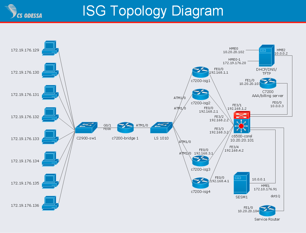
Network Diagram Software ISG Network Diagram


HelpDesk
How to Create a Network Security Diagram

"A computer network or data network is a telecommunications network that allows computers to exchange data. In computer networks, networked computing devices (network nodes) pass data to each other along data connections. The connections (network links) between nodes are established using either cable media or wireless media. The best-known computer network is the Internet.
Network devices that originate, route and terminate the data are called network nodes. Nodes can include hosts such as servers and personal computers, as well as networking hardware. Two devices are said to be networked when a device is able to exchange information with another device." [Computer network. Wikipedia]
This computer communication network diagram example was created using the ConceptDraw PRO diagramming and vector drawing software extended with the Computer and Networks solution from the Computer and Networks area of ConceptDraw Solution Park.
Network diagram

Network Hubs

Hotel Network Topology Diagram


 Network Security Diagrams
The Network Security Diagrams solution presents a large collection of predesigned cybersecurity vector stencils, cliparts, shapes, icons and connectors to help you succeed in designing professional and accurate Network Security Diagrams, Network Security Infographics to share knowledge about effective ways of networks protection with help of software and network security devices of different cyber security degrees, Network Plans for secure wireless network, Computer Security Diagrams to visually tell about amazing possibilities of IT security solutions. The samples and examples reflect the power of ConceptDraw DIAGRAM software in drawing Network Security Diagrams, give the representation about variety of existing types of attacks and threats, help to realize their seriousness and the methods to deal with them.
Cisco Routers. Cisco icons, shapes, stencils and symbols

"... logical topology shows how data flows within a network, regardless of its physical design. ...
... mapping the data flow between the components determines the logical topology of the network." [Network topology. Wikipedia]
"In a shared media topology, all the systems have the ability to access the physical layout whenever they need it. The main advantage in a shared media topology is that the systems have unrestricted access to the physical media. Of course, the main disadvantage to this topology is collisions. If two systems send information out on the wire at the same time, the packets collide and kill both packets. Ethernet is an example of a shared media topology. ...
The token-based topology works by using a token to provide access to the physical media. In a token-based network, there is a token that travels around the network. When a system needs to send out packets, it grabs the token off of the wire, attaches it to the packets that are sent, and sends it back out on the wire. As the token travels around the network, each system examines the token. When the packets arrive at the destination systems, those systems copy the information off of the wire and the token continues its journey until it gets back to the sender. When the sender receives the token back, it pulls the token off of the wire and sends out a new empty token to be used by the next machine." [Logical topology. Wikipedia]
This Cisco logical computer network diagram example was created using the ConceptDraw PRO diagramming and vector drawing software extended with the Cisco Network Diagrams solution from the Computer and Networks area of ConceptDraw Solution Park.
Logical network diagram
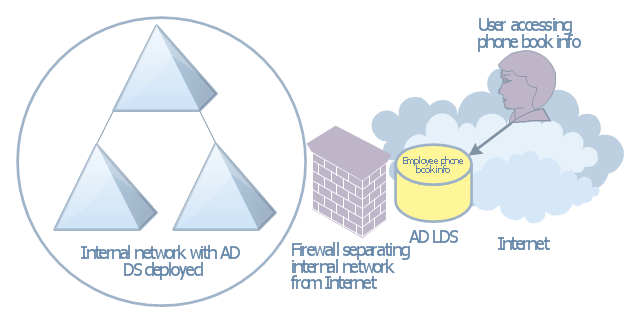
This AD diagram example was created based on the picture "AD LDS as a phone book service" from the book "Active Directory for Dummies".
"Directory services are a great way of providing information that can be fre-
quently retrieved and searched on in a hierarchical way. ... Well, there’s no reason that you can’t create a directory service that’s actually a phone book. Imagine that you need to make a searchable phone directory of your organization available on the Internet. ... This isn’t a difficult task, but it has security repercussions. If you’ve already deployed AD DS and you have the employees’ phone numbers available in that directory, it might not be a good idea to expose your AD DS environment to the Internet for security reasons. Using AD LDS is a great alternative because it can be deployed separately from AD DS and it’s designed to simply provide the information retrieval service that you need without the complications involved with Kerberos authentication and group policies." [Steve Clines and Marcia Loughry, Active Directory® For Dummies®, 2nd Edition. 2008]
The Active Directory diagram example "AD LDS as a phone book service" was created using the ConceptDraw PRO diagramming and vector drawing software extended with the Active Directory Diagrams solution from the Computer and Networks area of ConceptDraw Solution Park.
Active Directory network diagram
- Diagram Of Firewall Computer
- Firewall between LAN and WAN | Network Security Diagrams ...
- Hardware Firewall
- Firewall between LAN and WAN | Network diagrams with ...
- Diagrams Of Firewall
- Draw The Diagram Of Firewall Subject Computer
- Fishbone Diagram For Firewall
- Network Gateway Router | Communication network diagram ...
- Firewall between LAN and WAN | Network Security Devices ...
- Diagram Of Firewall
- How To use Switches in Network Diagram | Computer network ...
- Use Of A Hardware Firewall With A Diagram
- Router Firewall Switch Diagram
- Fully Connected Network Topology Diagram | Local area network ...
- Spread of Conficker worm | Entity-Relationship Diagram (ERD ...
- Internet symbols - Vector stencils library | UML activity diagram ...
- Communication network diagram | Network Glossary Definition ...
- Network Diagram Cloud Firewall Workstation Switch Server
- How Are Worked Firewall Between Lan And Van Witdiagram
- Communication network diagram | Network Glossary Definition ...