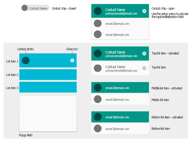
The vector stencils library "Android chips" contains 14 chip elements: contact chips, list items, popup field, contact photo, close icon.
Use it to design user interface of your Android application.
The shapes example "Design elements - Android chips" was created using the ConceptDraw PRO diagramming and vector drawing software extended with the "Android user interface" solution from the "Software Development" area of ConceptDraw Solution Park.
Chip elements
 Android User Interface
The Android User Interface solution allows ConceptDraw PRO act as an Android UI design tool. Libraries and templates contain a variety of Android GUI elements to help users create images based on Android UI design.
Structured Systems Analysis and Design Method (SSADM) with ConceptDraw PRO

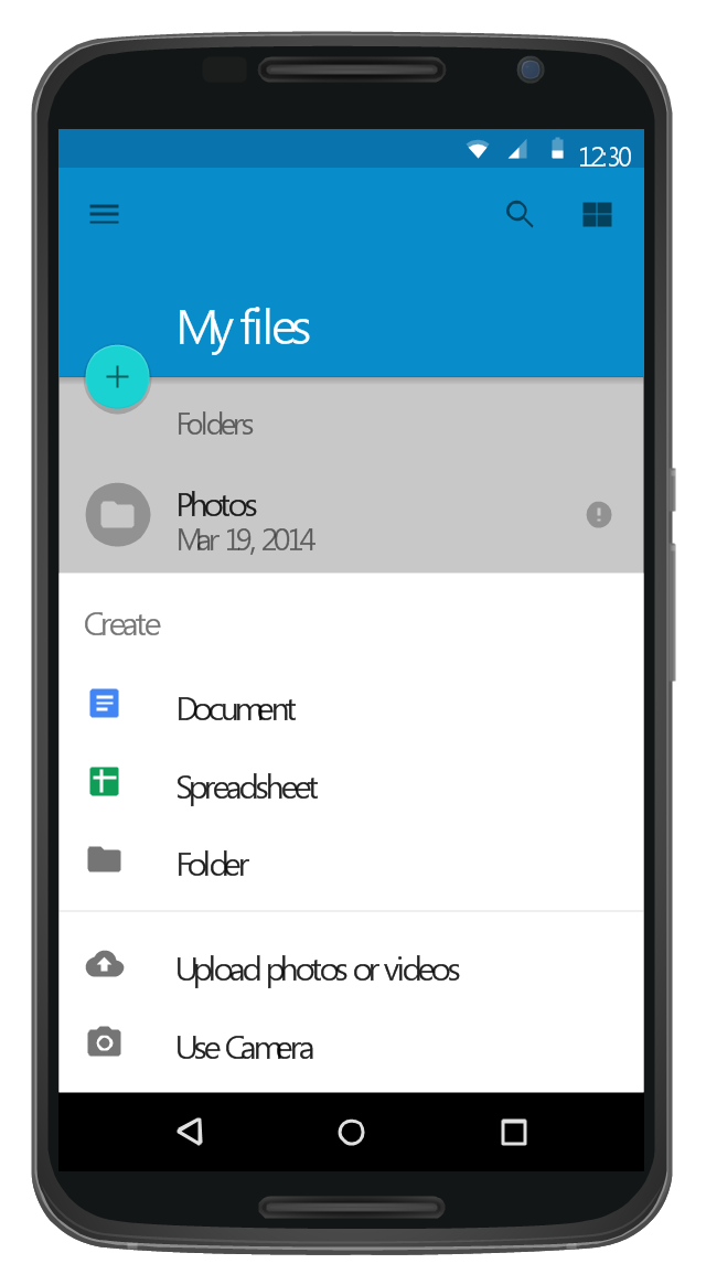
This Android 5 UI design example shows My Files screen of Google Nexus 6 smartphone.
The user interface design example "Android 5.0 - List-style bottom sheet" was created using the ConceptDraw PRO diagramming and vector drawing software extended with the "Android user interface" solution from the "Software Development" area of ConceptDraw Solution Park.
The user interface design example "Android 5.0 - List-style bottom sheet" was created using the ConceptDraw PRO diagramming and vector drawing software extended with the "Android user interface" solution from the "Software Development" area of ConceptDraw Solution Park.
List-style bottom sheet UI
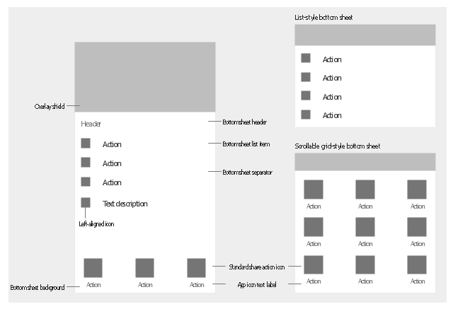
The vector stencils library "Android bottom sheets" contains 11 bottom sheet elements.
Use it to design user interface of your Android application.
The shapes example "Design elements - Android bottom sheets" was created using the ConceptDraw PRO diagramming and vector drawing software extended with the "Android user interface" solution from the "Software Development" area of ConceptDraw Solution Park.
Bottom sheet elements
UML Diagram Types List

FSM — Finite-state Machine

ERD Symbols and Meanings


 Windows 10 User Interface
Windows 10 User Interface solution extends significantly ConceptDraw PRO v11 functionality with look-and-feel functions of GUI software and makes it a great assistant for Win10 designers, developers, and software engineers. This solution provides a wide s
 Computer Network Diagrams
Computer Network Diagrams solution extends ConceptDraw PRO software with samples, templates and libraries of vector icons and objects of computer network devices and network components to help you create professional-looking Computer Network Diagrams, to plan simple home networks and complex computer network configurations for large buildings, to represent their schemes in a comprehensible graphical view, to document computer networks configurations, to depict the interactions between network's components, the used protocols and topologies, to represent physical and logical network structures, to compare visually different topologies and to depict their combinations, to represent in details the network structure with help of schemes, to study and analyze the network configurations, to communicate effectively to engineers, stakeholders and end-users, to track network working and troubleshoot, if necessary.
Finite State Machine

How To use House Electrical Plan Software


- Android List Item Design
- Design elements - Android chips | Android User Interface | Android ...
- Design elements - Android chips
- Android 5.0 - List -style bottom sheet | Flowchart design . Flowchart ...
- Design elements - Management list blocks | Design elements ...
- Design elements - Android bottom sheets | Android 5.0 - List -style ...
- Design elements - Android bottom sheets | Android UI Design ...
- Design elements - Management list blocks | Design elements - List ...
- Design elements - Text blocks | Design elements - Android chips ...
- Single-line grid list | Android User Interface | Design elements ...
- Android Ui Design Software
- Design elements - Bulleted and numbered lists | Design elements ...
- Design elements - Android chips | Diagramming Software for Design ...
- Full-screen dialog | Single-line grid list | Contact chips | Android ...
- Android List With Icons Design
- Types of Flowcharts | Android GUI | Specification and Description ...
- Android Ui Design Examples
- Android Software Ui Design
- Top 5 Android Flow Chart Apps | Android UI Design Tool | Android ...
- Design Description Language