Electrical Symbols — Terminals and Connectors

Electrical Symbols — Qualifying

Electrical Symbols — Composite Assemblies

Electrical Symbols — Transmission Paths

Electrical Symbols, Electrical Diagram Symbols

Electrical Symbols — Inductors

Electrical Symbols — Delay Elements

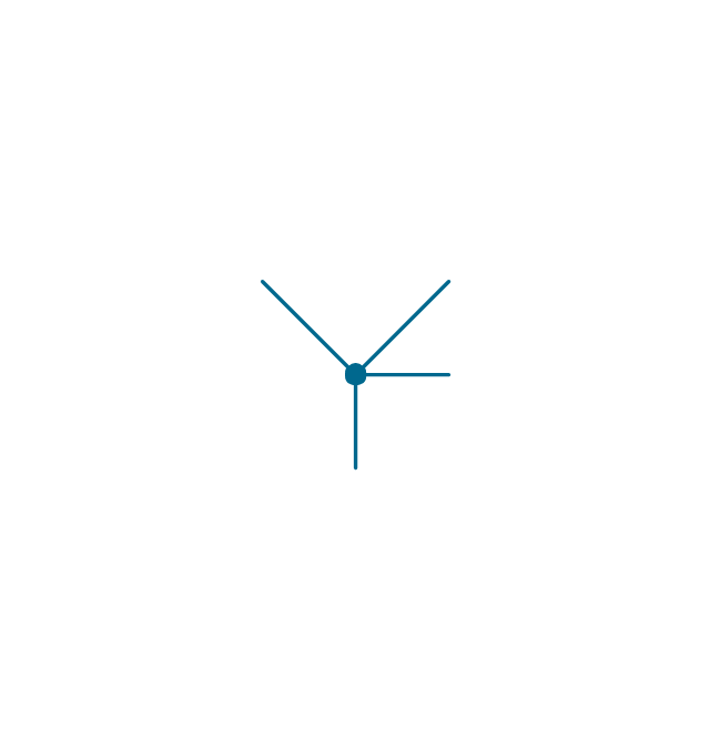
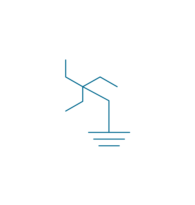
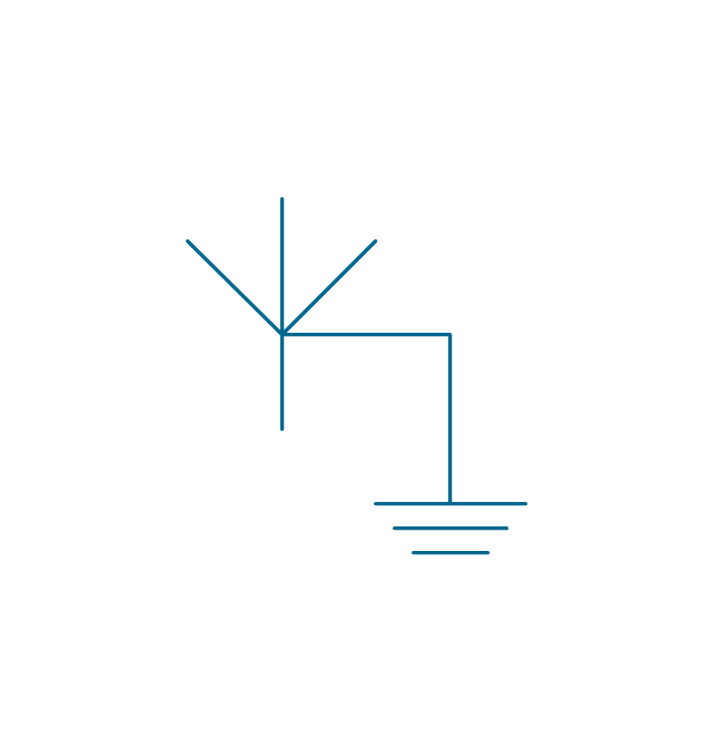
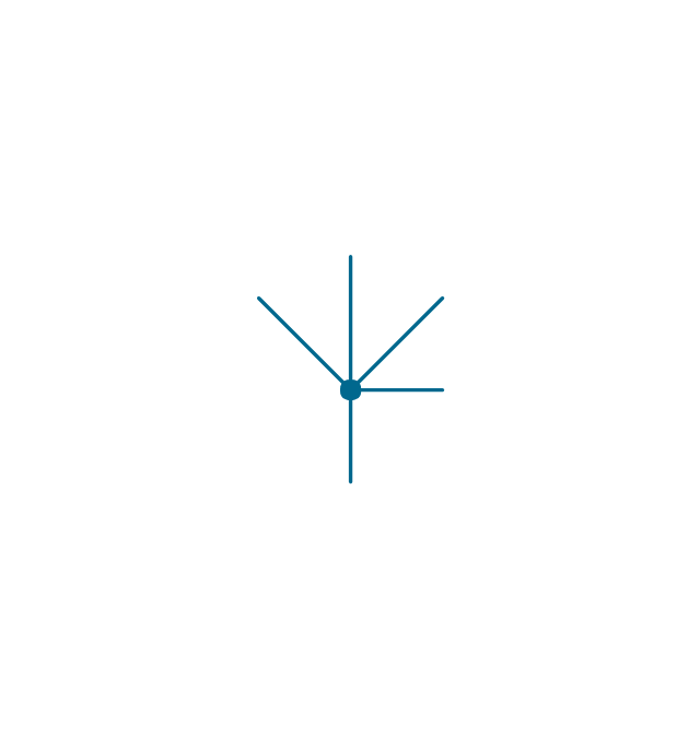
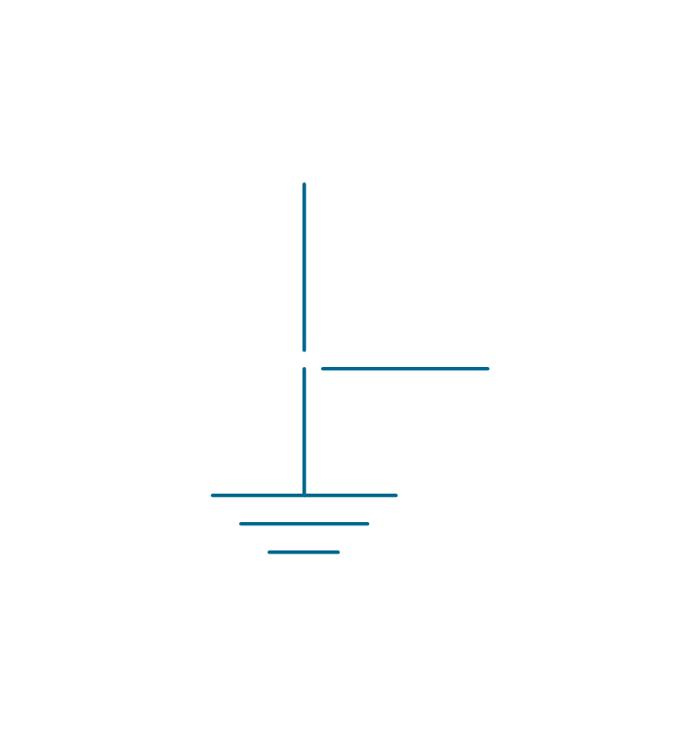
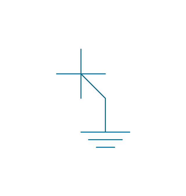
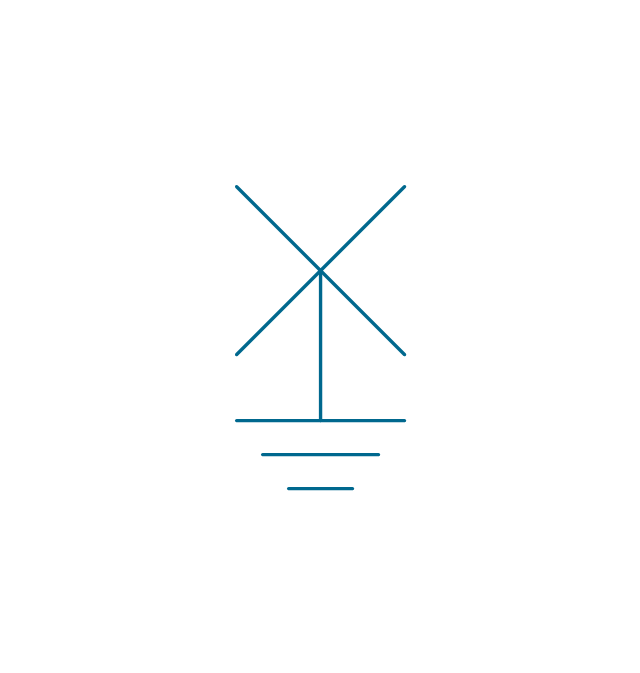
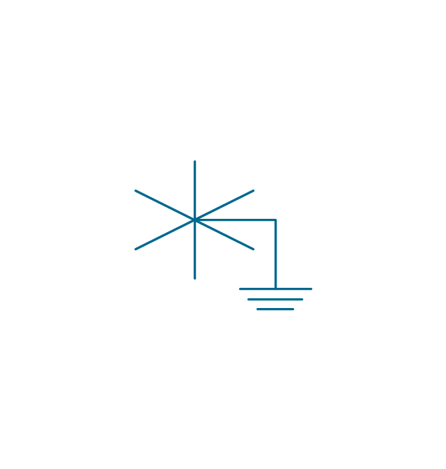
The vector stencils library "Qualifying" contains 56 qualifying symbols.
Use these shapes to annotate or specify characteristics of objects in electrical drawings, electronic schematics, circuit diagrams, electromechanical drawings, and wiring diagrams, cabling layout diagrams in the ConceptDraw PRO diagramming and vector drawing software extended with the Electrical Engineering solution from the Engineering area of ConceptDraw Solution Park.
www.conceptdraw.com/ solution-park/ engineering-electrical
Positive polarity

Negative polarity

Neutral symbol

6-phase double delta

Electret

Radiation, non-ion.
Radiation, ion.
Radiation, non-ion., coherent
Radiation, ion., coherent
Radiation, non-ion. 2
Radiation, ion. 2
Radiation, non-ion., coherent 2
Radiation, ion., coherent 2
Multiple-phase
Multiple-phase 2

Multiple-phase, interconnect.
Multiple-phase, interconnect. 2
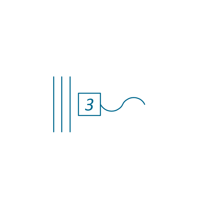
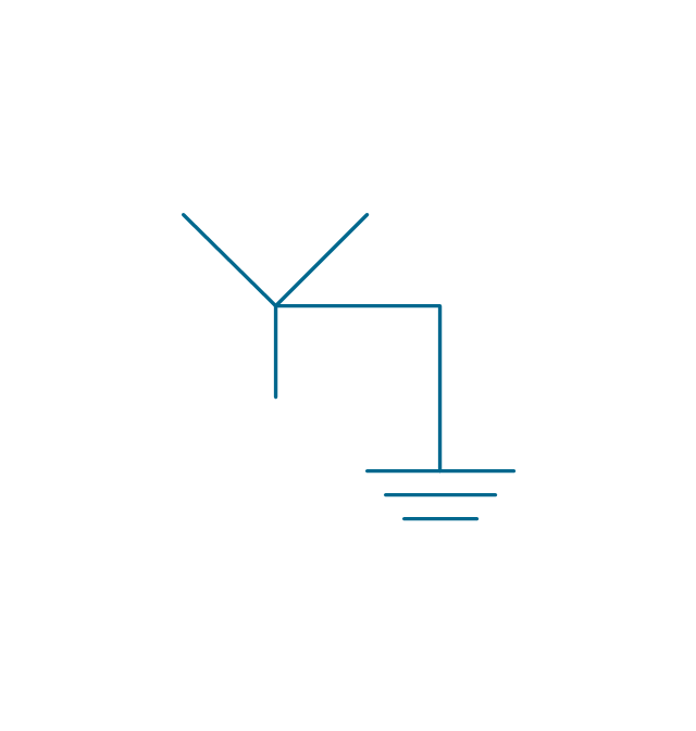
3 separate windings
3 separate windings, interconnect.
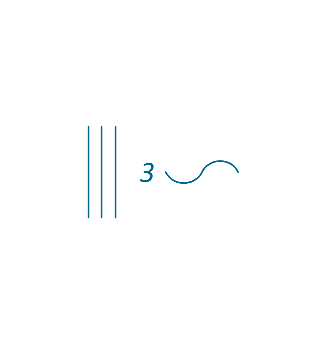
3 separate windings, interconnect. 2
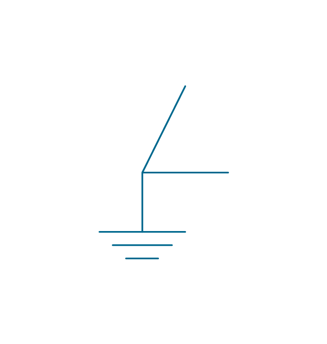
3-phase (V)
-qualifying---vector-stencils-library.png--diagram-flowchart-example.png)
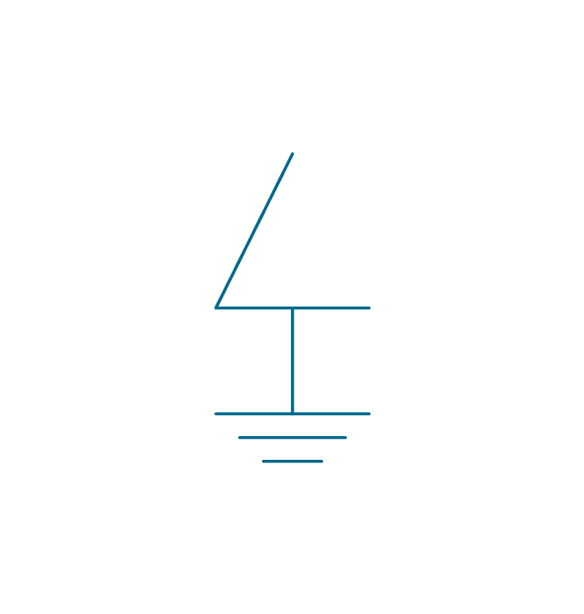
3-Phase (T)
-qualifying---vector-stencils-library.png--diagram-flowchart-example.png)
3-phase delta 3

3-phase delta 1

3-phase delta 1, grounded
3-phase delta 2
3-phase delta 2, grounded
3-phase delta 2, grounded 2
3-phase delta 4

3-phase delta 4, grounded
3-phase star, general

3-phase star, grounded
3-phase star, neutral brought out
3-phase zigzag

3-phase zigzag, grounded
3-phase 4-wire, general

3-phase 4-wire, grounded
3-phase 4-wire, neutral brought out
2-phase 3-wire

2-phase 3-wire, separated

2-phase 3-wire, grounded

2-phase 3-wire, separat., ground.
2-phase 4-wire

2-phase 4-wire, grounded
4-phase, general

4-phase, grounded
4-phase, neutral brought out

6-phase double star

6-phase double star, grounded
6-phase double star 2

6-phase double star, grounded 2
6-phase polygon

6-phase fork
6-phase fork, neutral

Special connector

Coaxial symbol
Electrical Diagram

The vector stencils library "Qualifying" contains 56 qualifying symbols of radiation, polarity, phase, windings, wire, ground, connection, connector, coaxial, electret.
Use these signs to annotate or specify characteristics of objects in electrical drawings, electronic schematics, circuit diagrams, electromechanical drawings, and wiring diagrams, cabling layout diagrams.
"An electrical drawing, is a type of technical drawing that shows information about power, lighting, and communication for an engineering or architectural project. Any electrical working drawing consists of "lines, symbols, dimensions, and notations to accurately convey an engineering's design to the workers, who install the electrical system on the job".
A complete set of working drawings for the average electrical system in large projects usually consists of:
(1) A plot plan showing the building's location and outside electrical wiring.
(2) Floor plans showing the location of electrical systems on every floor.
(3) Power-riser diagrams showing panel boards.
(4) Control wiring diagrams.
(5) Schedules and other information in combination with construction drawings.
Electrical drafters prepare wiring and layout diagrams used by workers who erect, install, and repair electrical equipment and wiring in communication centers, power plants, electrical distribution systems, and buildings." [Electrical drawing. Wikipedia]
The signs example "Design elements - Qualifying" was drawn using the ConceptDraw PRO diagramming and vector drawing software extended with the Electrical Engineering solution from the Engineering area of ConceptDraw Solution Park.
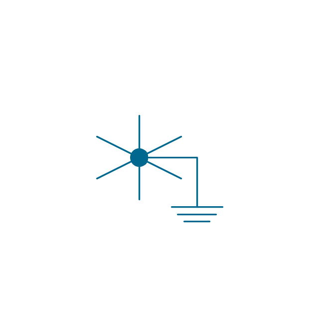
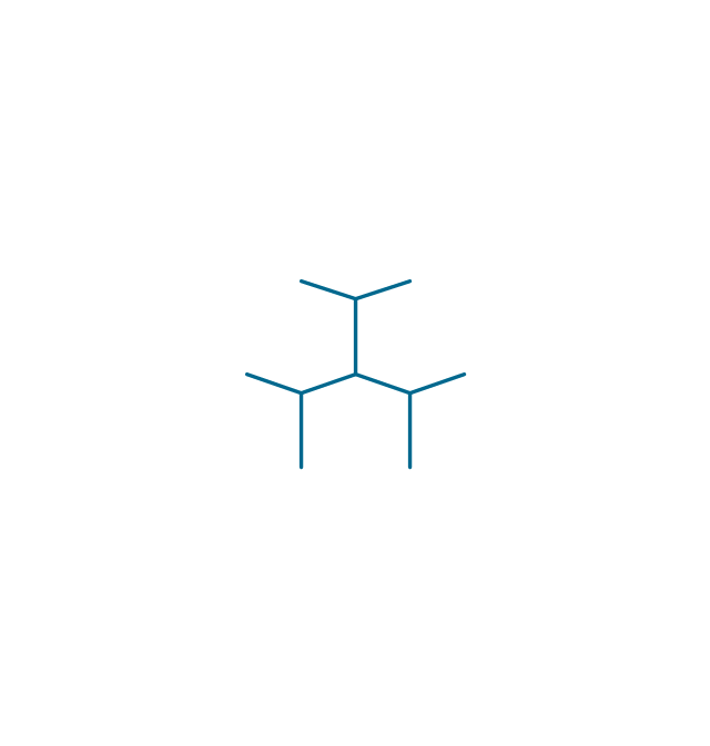
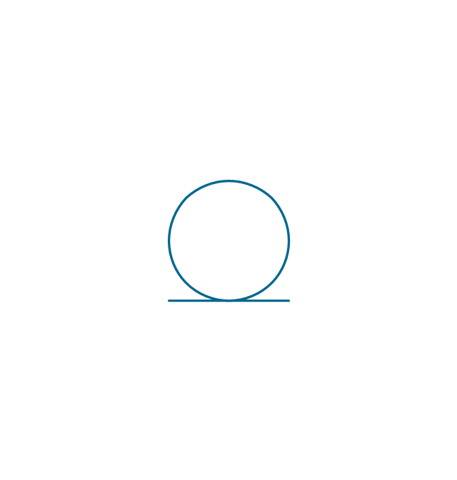
Qualifying symbols

Process Flowchart


Mechanical Drawing Software

How To use House Electrical Plan Software


How To use Electrical and Telecom Plan Software


- 3 Wire Electrical Wiring Diagram
- Electrical Symbols — Terminals and Connectors | Electrical Symbols ...
- Wire Direction Symbols
- Electrical Symbols — Qualifying | Qualifying - Vector stencils library ...
- Electrical Wiring Connectors Symbol
- Electrical Symbols — Terminals and Connectors | Terminals and ...
- Connectors Symbol For Electrical Circuit
- Wire To Wire Conection Symbol
- Electrical Symbols — Terminals and Connectors | How To use ...
- Audio & Video Connector Types | Design elements - Terminals and ...
- Terminal And Connectors Symbol
- Coaxial Cable Schematic Symbol
- Terminal And Connector Symbol
- Design elements - Terminals and connectors | Electrical Symbols ...
- Symbol Of Distribution Board Of Three Phase
- Electrical Symbols — Terminals and Connectors | How To use ...
- Design elements - Terminals and connectors | Electrical Symbols ...
- Electrical Symbols , Electrical Diagram Symbols | Electrical Drawing ...
- 3 Phase Distribution Board Wiring Diagram Symbol