HelpDesk
How to Connect Objects on PC


HelpDesk
How to Set Line Jumps for Smart Connectors in ConceptDraw PRO

Electrical Symbols — Terminals and Connectors

HelpDesk
How to Add and Edit Text on Connectors

Basic Flowchart Symbols and Meaning


Audio & Video Connector Types

Audio and Video Connector

The vector stencils library "Terminals and connectors" contains 43 element symbols of terminals, connectors, plugs, polarized connectors, jacks, coaxial cables, and conductors.
Use it for drawing the wiring diagrams, electrical layouts, electronic schematics, and circuit diagrams.
"An electrical connector is an electro-mechanical device for joining electrical circuits as an interface using a mechanical assembly. Connectors consist of plugs (male-ended) and jacks (female-ended). The connection may be temporary, as for portable equipment, require a tool for assembly and removal, or serve as a permanent electrical joint between two wires or devices. An adapter can be used to effectively bring together dissimilar connectors.
There are hundreds of types of electrical connectors. Connectors may join two lengths of flexible copper wire or cable, or connect a wire or cable or optical interface to an electrical terminal.
In computing, an electrical connector can also be known as a physical interface... Cable glands, known as cable connectors in the US, connect wires to devices mechanically rather than electrically and are distinct from quick-disconnects performing the latter." [Electrical connector. Wikipedia]
"A terminal is the point at which a conductor from an electrical component, device or network comes to an end and provides a point of connection to external circuits. A terminal may simply be the end of a wire or it may be fitted with a connector or fastener. In network analysis, terminal means a point at which connections can be made to a network in theory and does not necessarily refer to any real physical object. In this context, especially in older documents, it is sometimes called a "pole".
The connection may be temporary, as seen in portable equipment, may require a tool for assembly and removal, or may be a permanent electrical joint between two wires or devices.
All electric cell have two terminals. The first is the positive terminal and the second is the negative terminal. The positive terminal looks like a metal cap and the negative terminal looks like a metal disc. The current flows from the positive terminal, and out through the negative terminal, replicative of current flow (positive (+) to negative (-) flow)." [Terminal (electronics). Wikipedia]
The shapes example "Design elements - Terminals and connectors" was drawn using the ConceptDraw PRO diagramming and vector drawing software extended with the Electrical Engineering solution from the Engineering area of ConceptDraw Solution Park.
Terminal and connector symbols

This pinout diagram example showing a VGA connector (as viewed from the socket) was redesigned from the Wikimedia Commons file: DE15 Connector Pinout.svg. [commons.wikimedia.org/ wiki/ File:DE15_ Connector_ Pinout.svg]
"A Video Graphics Array (VGA) connector is a three-row 15-pin DE-15 connector. The 15-pin VGA connector is found on many video cards, computer monitors, and high definition television sets. On laptop computers or other small devices, a mini-VGA port is sometimes used in place of the full-sized VGA connector.
DE-15 is also conventionally called RGB connector, D-sub 15, mini sub D15, mini D15, DB-15, HDB-15, HD-15 or HD15 (High Density, to distinguish it from the older and less flexible DE-9 connector used on some older VGA cards, which has the same shell size but only two rows of pins).
VGA connectors and cables carry analog component RGBHV (red, green, blue, horizontal sync, vertical sync) video signals, and VESA Display Data Channel (VESA DDC) data. In the original version of DE-15 pinout, one pin was keyed by plugging the female connector hole; this prevented non-VGA 15 pin cables from being plugged into a VGA socket. Four pins carried Monitor ID bits which were rarely used; VESA DDC redefined some of these pins and replaced the key pin with +5 V DC power supply.
The VGA interface is not engineered to be hotpluggable (so that the user can connect or disconnect the output device while the host is running), although in practice this can be done and usually does not cause damage to the hardware or other problems. However, nothing in the design ensures that the ground pins make a connection first and break last, so hotplugging may introduce surges in signal lines which may or may not be adequately protected against. Also, depending on the hardware and software, detecting a monitor being connected might not work properly in all cases." [VGA connector. Wikipedia]
The pinout diagram example "VGA connector pinout" was created using the ConceptDraw PRO diagramming and vector drawing software extended with the Audio and Video Connectors solution from the Engineering area of ConceptDraw Solution Park.
VGA connector pinout

ConceptDraw Arrows10 Technology

ConceptDraw Arrows10 Technology

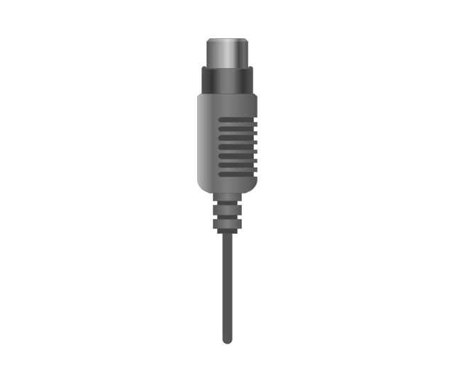
The vector stencils library "Audio and video connectors" contains 94 symbols of audio and video connectors and device silhouettes.
Use these jacks and plugs clipart icons for drawing hook up diagrams in the ConceptDraw PRO diagramming and vector drawing software extended with the Audio and Video Connectors solution from the Engineering area of ConceptDraw Solution Park.
www.conceptdraw.com/ solution-park/ engineering-audio-video-connectors
Device 1

Device 2

TV

Cable, thin

Cable, thick

Device 1, half part

Device 2, half part

TRS plug, purple
TRS plug, brown
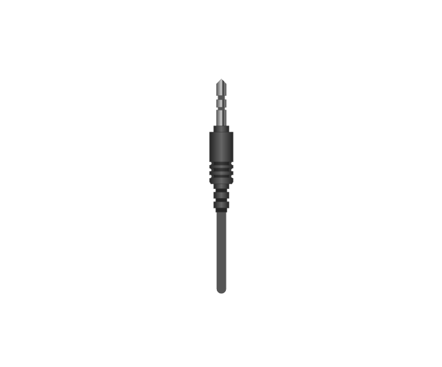
TRS plug, black

TRS plug, gray
TRS plug, blue
TRS plug, green
TRS jack, purple

TRS jack, brown

TRS jack, black

TRS jack, gray

TRS jack, blue

TRS jack, green

TRS plug, micro-jack
TRS, micro-jack

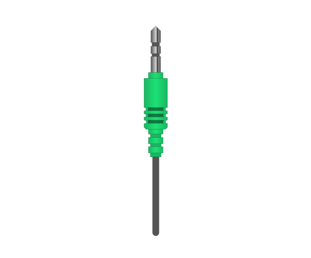
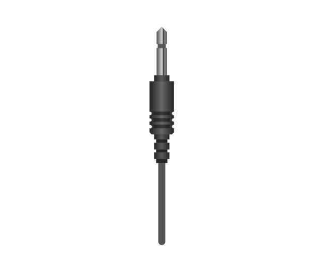
Headphone Mini Jack Cable
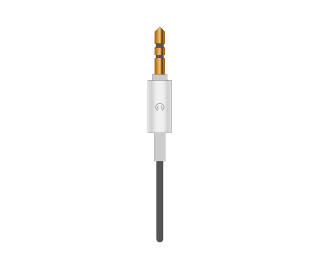
Headphone Mini Jack

Microphone Mini Jack Cable
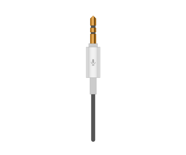
Microphone Mini Jack

XLR female Neutrik
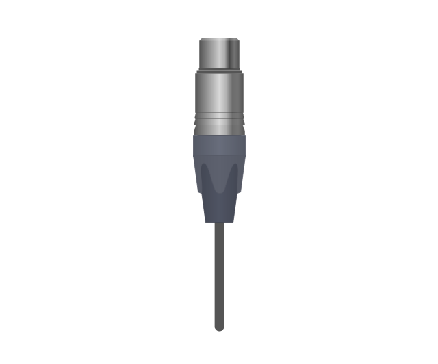
XLR female Neutrik

TOSLINK Optical Audio Cable, blue
TOSLINK Optical Audio Cable
TOSLINK Optical jack

TOSLINK Optical jack, blue

DVI plug
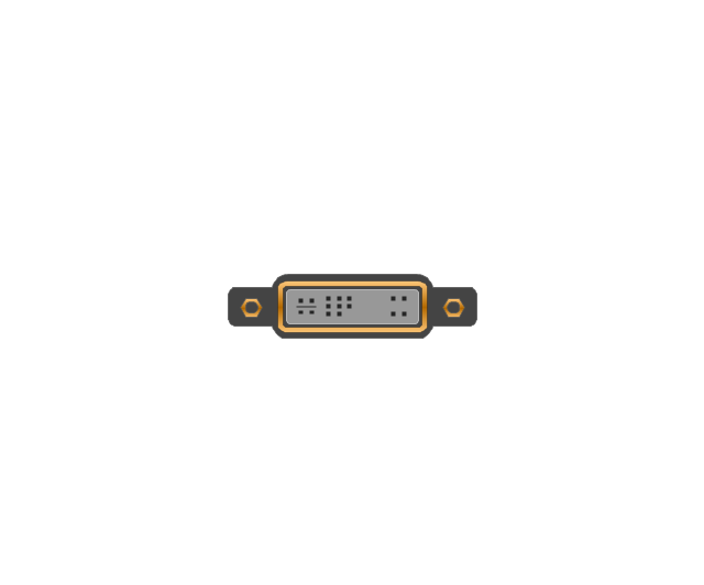
DVI-I (Single Link) jack
-jack-audio-and-video-connectors---vector-stencils-library.png--diagram-flowchart-example.png)
DVI-I (Dual Link) jack
-jack-audio-and-video-connectors---vector-stencils-library.png--diagram-flowchart-example.png)
DVI-D (Single Link) jack
-jack-audio-and-video-connectors---vector-stencils-library.png--diagram-flowchart-example.png)
DVI-D (Dual Link) jack
-jack-audio-and-video-connectors---vector-stencils-library.png--diagram-flowchart-example.png)
DVI-A Port
DVI-I (Single Link)
-audio-and-video-connectors---vector-stencils-library.png--diagram-flowchart-example.png)
DVI-I (Dual Link)
-audio-and-video-connectors---vector-stencils-library.png--diagram-flowchart-example.png)
DVI-D (Single Link)
-audio-and-video-connectors---vector-stencils-library.png--diagram-flowchart-example.png)
DVI-D (Dual Link)
-audio-and-video-connectors---vector-stencils-library.png--diagram-flowchart-example.png)
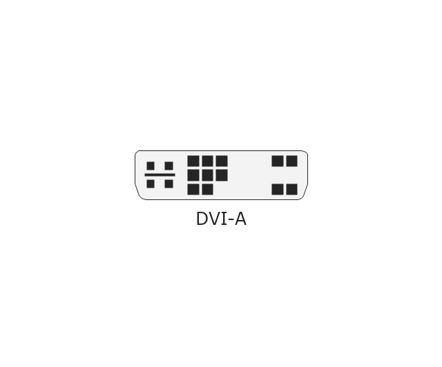
DVI-A
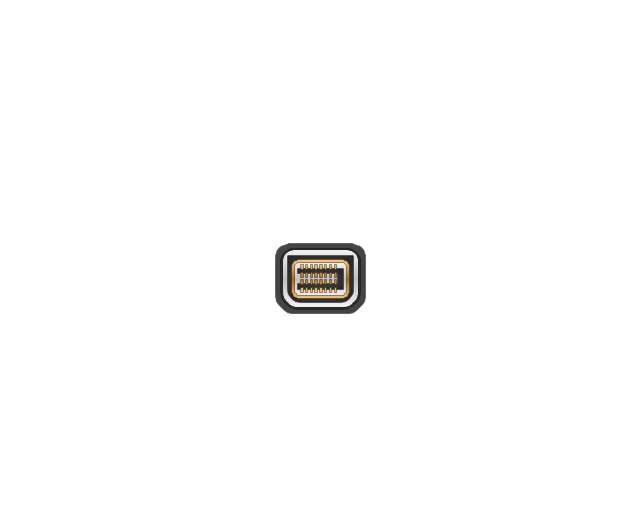
Mini DVI jack
Mini DVI plug
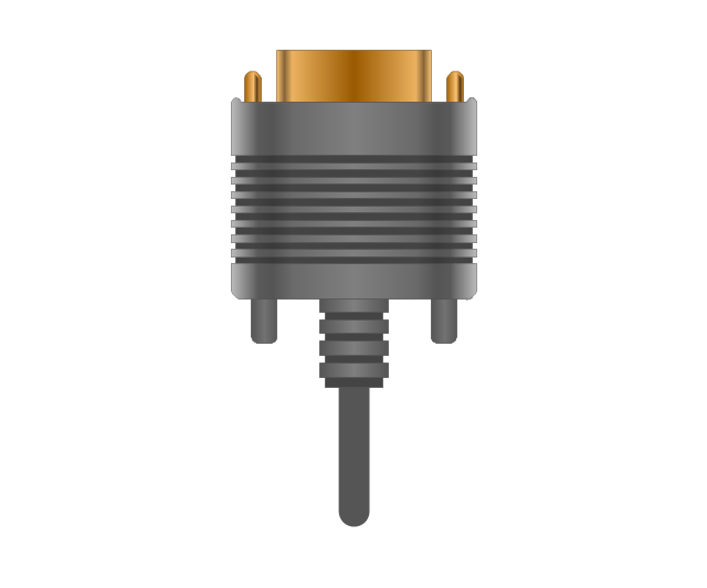
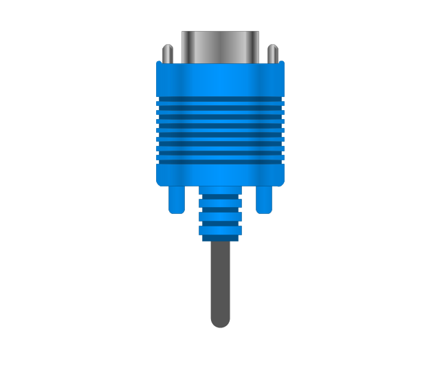
VGA plug
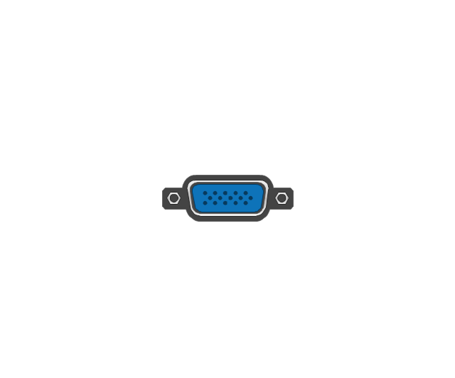
VGA jack
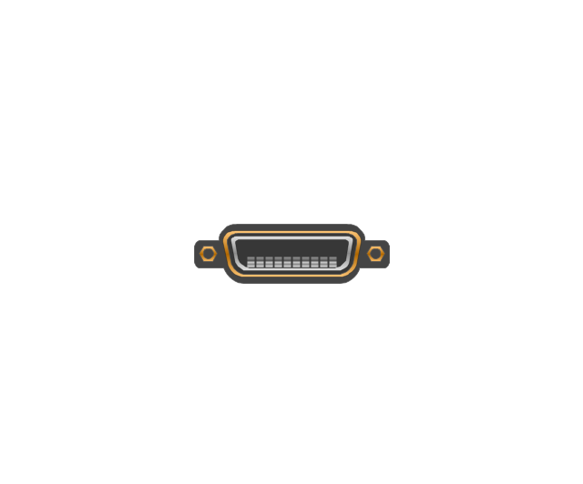
DFP jack
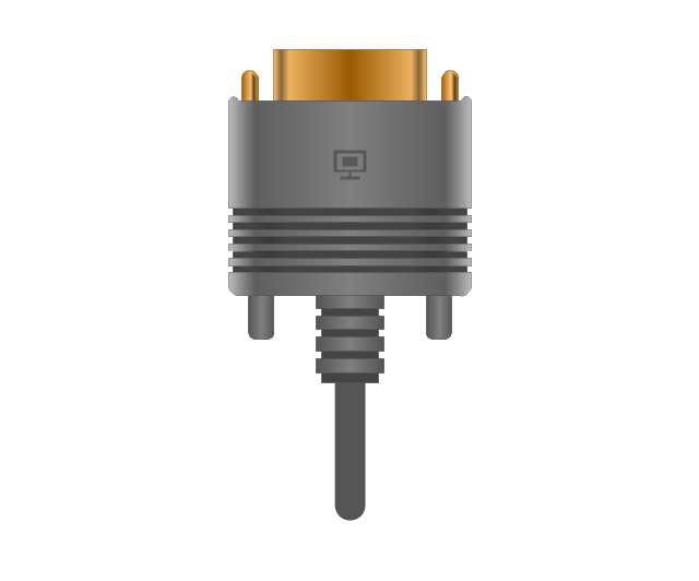
DFP plug
S-Video plug
S-Video IN

S-Video OUT

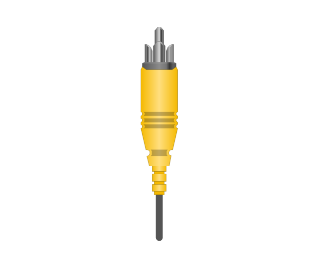
RCA, yellow

RCA, yellow
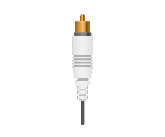
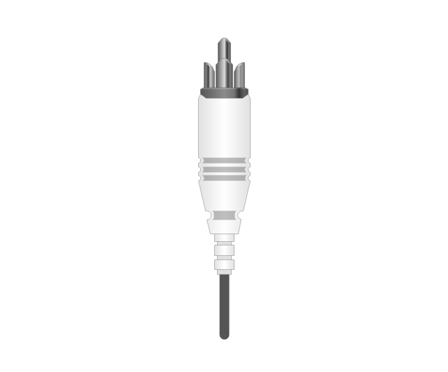
RCA, white

RCA, white
RCA, red

RCA, red

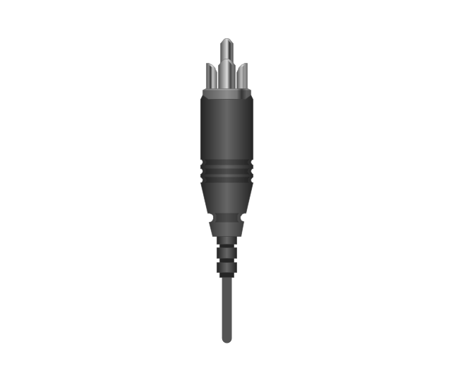
RCA, black

RCA, black
RCA, green

RCA, green
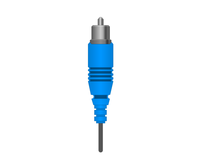
RCA, blue

RCA, blue
RCA, gray

RCA, gray
RCA, brown

RCA, brown
RCA, tan

RCA, tan
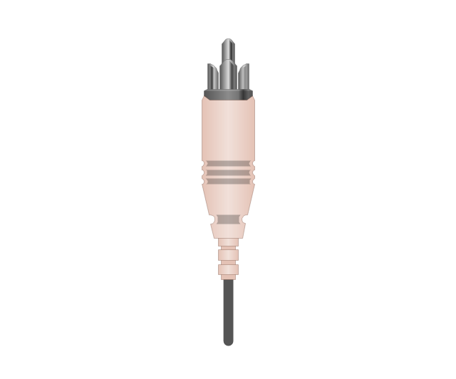
RCA, purple
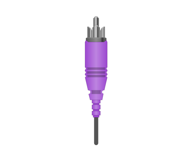
RCA, purple

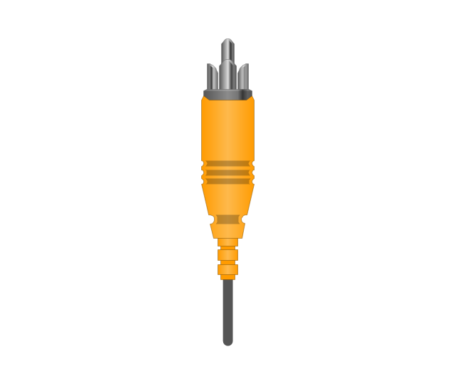
RCA, orange

RCA, orange
Display Port socket
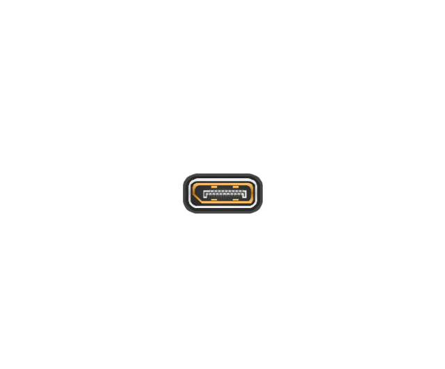
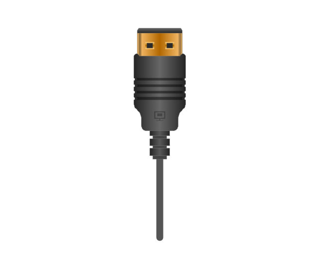
Display Port plug
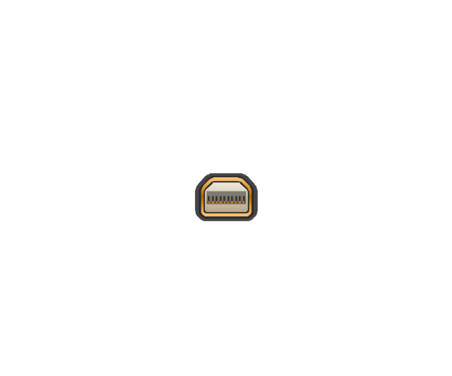
Mini Display port socket
Mini Display port socket, white

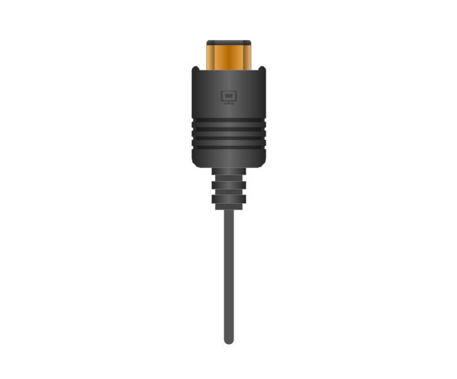
Mini Display port plug
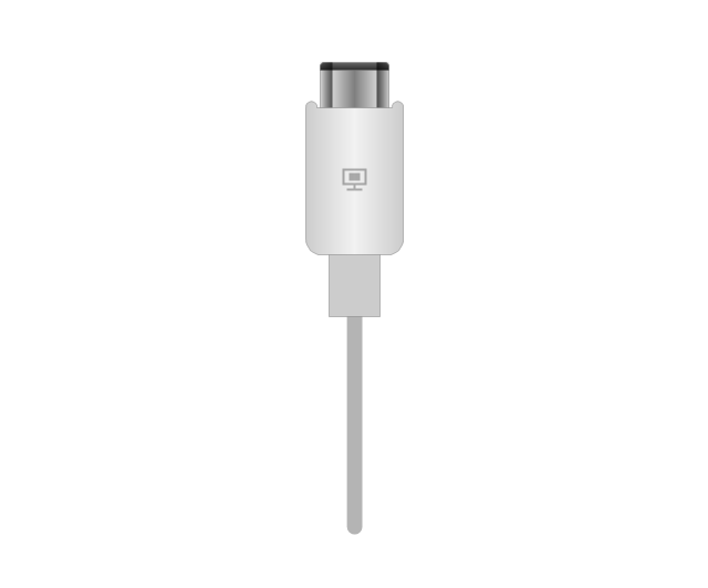
Mini Display port plug, white
HDMI jack
HDMI plug
HDMI plug, white
Thunderbolt jack
Thunderbolt plug
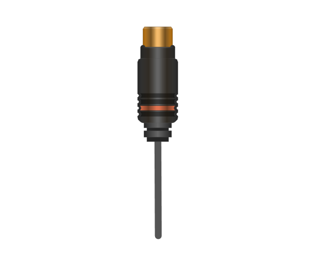
Coaxial TV plug
Coaxial TV jack

F connector jack

F connector plug
XLR male Neutrik

XLR male Neutrik
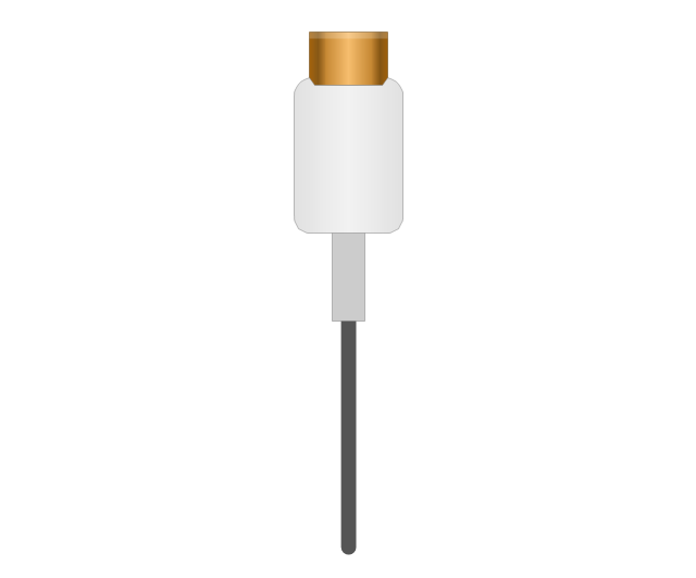
TS plug
TS jack

MIDI

MIDI
ConceptDraw Arrows10 Technology

UML Component Diagram. Design Elements
")

This AV connector pinout diagram example was redesigned from the Wikipedia file: DVI Connector Types.svg.
[en.wikipedia.org/ wiki/ File:DVI_ Connector_ Types.svg]
"Digital Visual Interface (DVI) is a video display interface developed by the Digital Display Working Group (DDWG). The digital interface is used to connect a video source to a display device, such as a computer monitor. It was developed with the intention of creating an industry standard for the transfer of digital video content.
The interface is designed to transmit uncompressed digital video and can be configured to support multiple modes such as DVI-D (digital only), DVI-A (analog only), or DVI-I (digital and analog). Featuring support for analog connections, the DVI specification is compatible with the VGA interface. This compatibility, along with other advantages, led to its widespread acceptance over competing digital display standards Plug and Display (P&D) and Digital Flat Panel (DFP). Although DVI is predominantly associated with computers, it is sometimes used in other consumer electronics such as television sets, video game consoles and DVD players." [Digital Visual Interface. Wikipedia]
The example "DVI connector types" was created using the ConceptDraw PRO diagramming and vector drawing software extended with the Audio and Video Connectors solution from the Engineering area of ConceptDraw Solution Park.
Male DVI connector pins (view of plug)
-dvi-connector-types.png--diagram-flowchart-example.png)
- On Page Connector Definition
- How to Set Line Jumps for Smart Connectors in ConceptDraw PRO ...
- Audio and video connectors - Vector stencils library
- Audio and video connectors - Vector stencils library | Audio and ...
- VGA connector pinout | Terminals and connectors - Vector stencils ...
- DVI connector types | Standard Universal Audio & Video Connection ...
- Audio and Video Connectors
- DVI pinout diagram | VGA connector pinout | Wiring Diagrams with ...
- DVI pinout diagram | DVI connector types | Dvi To Av Pinout Wiring
- Audio & Video Connector Types | Standard Universal Audio & Video ...
- How to Add Text to a Connector in ConceptDraw PRO | Swim Lane ...
- VGA connector pinout | Electrical Symbols, Electrical Diagram ...
- Audio & Video Connector Types | Design elements - Terminals and ...
- On Page Connector Andoff
- Electrical Symbols — Terminals and Connectors | How To use ...
- Connector Symbol In Flowchart
- VGA connector pinout | Audio and Video Connectors | DVI connector ...
- Basic Flowchart Symbols and Meaning | DVI connector types ...
- Audio & Video Connector Types
- VGA connector pinout | Audio Video Connections | Audio and Video ...