Electrical Symbols — Terminals and Connectors

Audio Visual Connectors Types

Audio & Video Connector Types
Standard Universal Audio & Video Connection Types
Basic Flowchart Symbols and Meaning


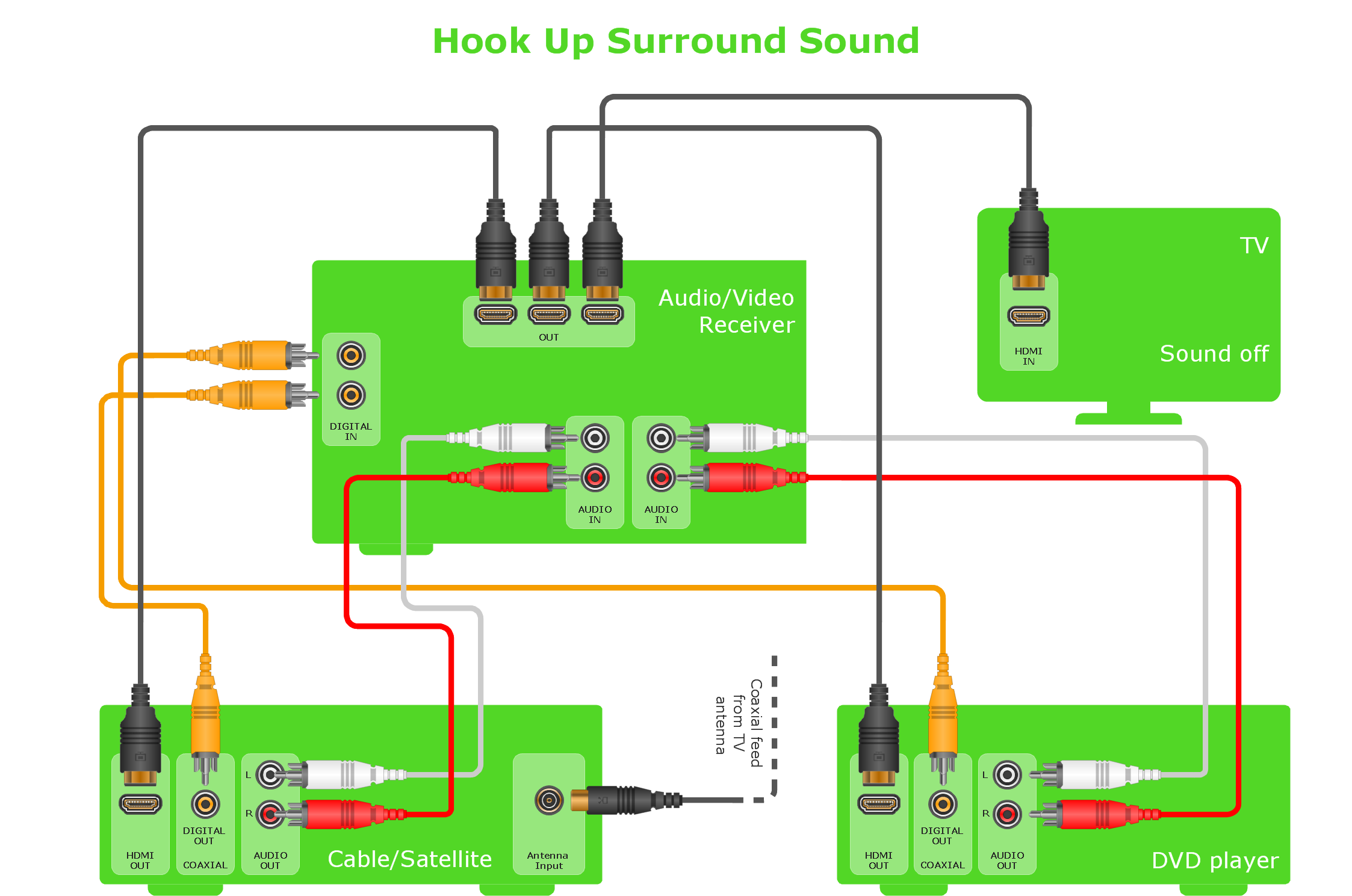
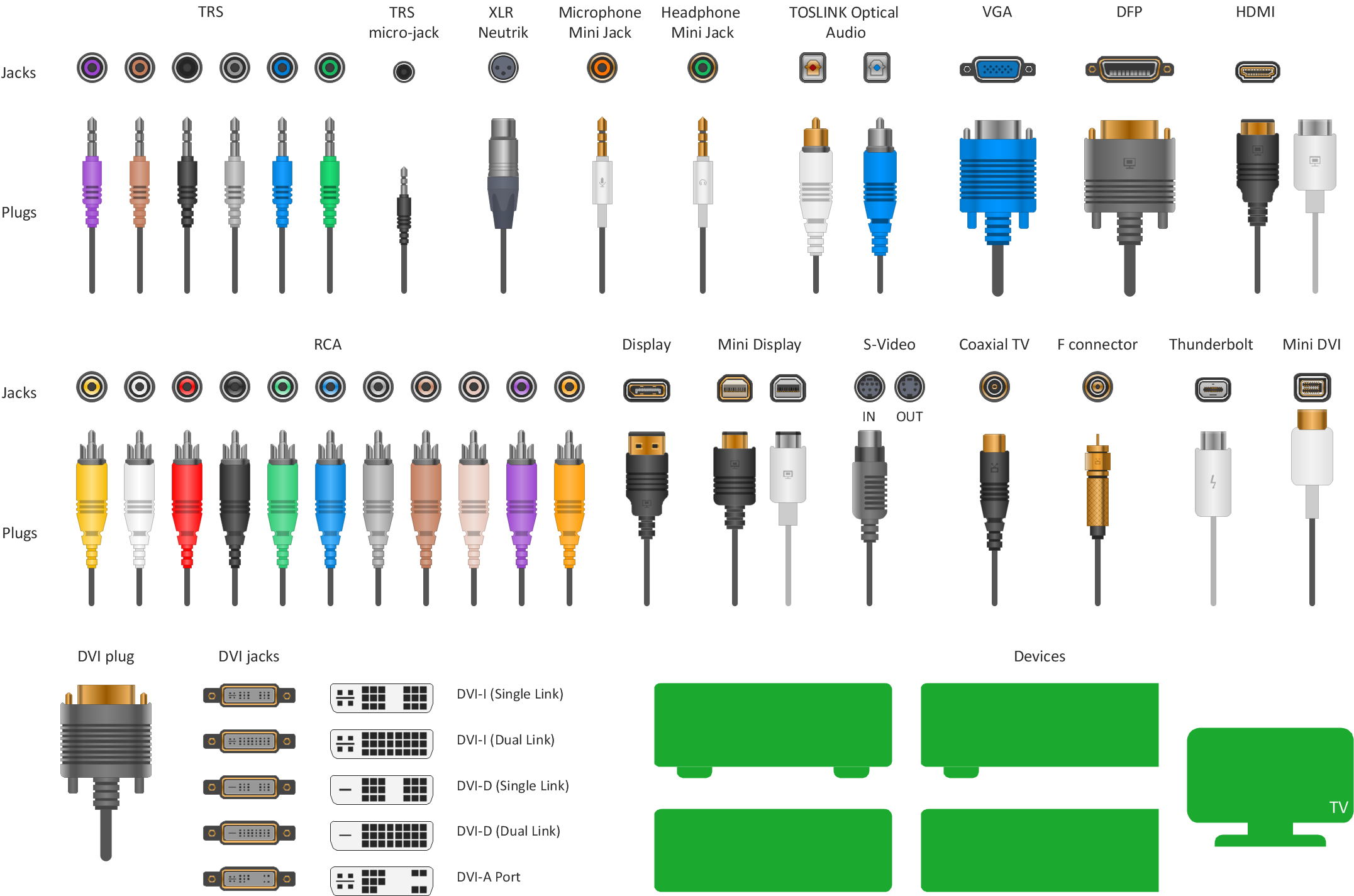
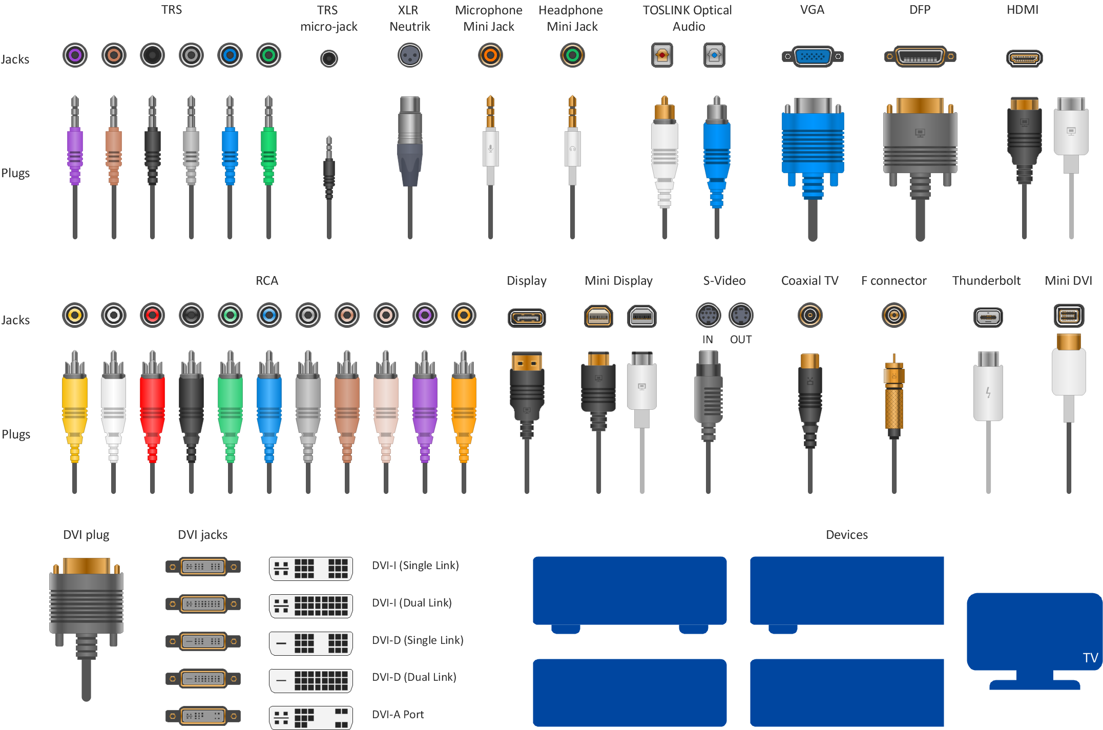
 Audio and Video Connectors
The Audio and Video Connectors solution contains a set of video connectors, audio connectors and s video connection; you will also find pre-designed objects, libraries, templates, and samples, allowing quick and easy diagramming of various configurations
This AV connector pinout diagram example was redesigned from the Wikipedia file: DVI Connector Types.svg.
[en.wikipedia.org/ wiki/ File:DVI_ Connector_ Types.svg]
"Digital Visual Interface (DVI) is a video display interface developed by the Digital Display Working Group (DDWG). The digital interface is used to connect a video source to a display device, such as a computer monitor. It was developed with the intention of creating an industry standard for the transfer of digital video content.
The interface is designed to transmit uncompressed digital video and can be configured to support multiple modes such as DVI-D (digital only), DVI-A (analog only), or DVI-I (digital and analog). Featuring support for analog connections, the DVI specification is compatible with the VGA interface. This compatibility, along with other advantages, led to its widespread acceptance over competing digital display standards Plug and Display (P&D) and Digital Flat Panel (DFP). Although DVI is predominantly associated with computers, it is sometimes used in other consumer electronics such as television sets, video game consoles and DVD players." [Digital Visual Interface. Wikipedia]
The example "DVI connector types" was created using the ConceptDraw PRO diagramming and vector drawing software extended with the Audio and Video Connectors solution from the Engineering area of ConceptDraw Solution Park.
Male DVI connector pins (view of plug)
-dvi-connector-types.png--diagram-flowchart-example.png)
Audio Connectors

Entity Relationship Diagram Symbols

Audio and Video Connector
- DVI connector types | Standard Universal Audio & Video Connection ...
- Types Of Connectors In Computer
- Network Cable Connector Types
- Types Of Network Connectors
- Audio & Video Connector Types | Audio Visual Connectors Types ...
- VGA connector pinout | DVI connector types | DVI pinout diagram ...
- Network Connector Types Audio Video System
- Network Diagram Software Backbone Network | Computer Network ...
- Wiring Diagrams with ConceptDraw PRO | Audio & Video Connector ...