Diagramming Software for Design UML Communication Diagrams


Communication Diagram UML2.0 / Collaboration UML1.x

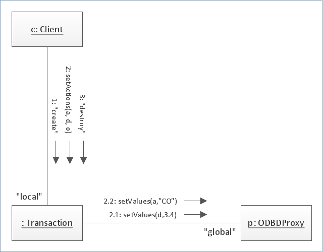
"The client–server model of computing is a distributed application structure that partitions tasks or workloads between the providers of a resource or service, called servers, and service requesters, called clients. Often clients and servers communicate over a computer network on separate hardware, but both client and server may reside in the same system. A server host runs one or more server programs which share their resources with clients. A client does not share any of its resources, but requests a server's content or service function. Clients therefore initiate communication sessions with servers which await incoming requests.
Examples of computer applications that use the client–server model are Email, network printing, and the World Wide Web." [Client–server model. Wikipedia]
The UML communication diagram example "Client server access" was created using the ConceptDraw PRO diagramming and vector drawing software extended with the Rapid UML solution from the Software Development area of ConceptDraw Solution Park.
UML communication diagram

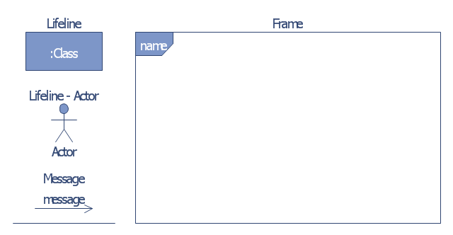
"Communication diagram (called collaboration diagram in UML 1.x) is a kind of UML interaction diagram which shows interactions between objects and/ or parts (represented as lifelines) using sequenced messages in a free-form arrangement.
Communication diagram corresponds (i.e. could be converted to/ from or replaced by) to a simple sequence diagram without structuring mechanisms such as interaction uses and combined fragments. It is also assumed that message overtaking (i.e., the order of the receptions are different from the order of sending of a given set of messages) will not take place or is irrelevant." [uml-diagrams.org/ communication-diagrams.html]
The template "UML communication diagram" for the ConceptDraw PRO diagramming and vector drawing software is included in the Rapid UML solution from the Software Development area of ConceptDraw Solution Park.
www.conceptdraw.com/ solution-park/ software-uml
UML communication diagram
Diagramming Software for Design UML Collaboration Diagrams

UML Use Case Diagram Example - Estate Agency

"Media (singular medium) are the storage and transmission channels or tools used to store and deliver information or data. It is often referred to as synonymous with mass media or news media, but may refer to any means of information communication. ...
Analog telecommunications include some radio systems, historical telephony systems, and historical TV broadcasts.
Digital telecommunications allow for computer-mediated communication, telegraphy, and computer networks.
Modern communication media now allow for intense long-distance exchanges between larger numbers of people (many-to-many communication via e-mail, Internet forums, and teleportation). On the other hand, many traditional broadcast media and mass media favor one-to-many communication (television, cinema, radio, newspaper, magazines, and also facebook)." [Media (communication). Wikipedia]
This communication medium diagram example was created using the ConceptDraw PRO diagramming and vector drawing software extended with the Telecommunication Network Diagrams solution from the Computer and Networks area of ConceptDraw Solution Park.
Telecommunication network diagram

The vector stencils library "Bank UML communication diagram" contains 4 shapes for drawing UML communication (collaboration) diagrams.
Use it for object-oriented modeling of your bank information system.
"A communication diagram in the Unified Modeling Language (UML) 2.0, is a simplified version of the UML 1.x collaboration diagram.
A Communication diagram models the interactions between objects or parts in terms of sequenced messages. Communication diagrams represent a combination of information taken from Class, Sequence, and Use Case Diagrams describing both the static structure and dynamic behavior of a system.
However, communication diagrams use the free-form arrangement of objects and links as used in Object diagrams. In order to maintain the ordering of messages in such a free-form diagram, messages are labeled with a chronological number and placed near the link the message is sent over. Reading a communication diagram involves starting at message 1.0, and following the messages from object to object." [Communication diagram. Wikipedia]
This example of UML communication diagram symbols for the ConceptDraw PRO diagramming and vector drawing software is included in the ATM UML Diagrams solution from the Software Development area of ConceptDraw Solution Park.
UML communication diagram symbols
 Telecommunication Network Diagrams
Telecommunication Network Diagrams solution extends ConceptDraw PRO software with samples, templates, and great collection of vector stencils to help the specialists in a field of networks and telecommunications, as well as other users to create Computer systems networking and Telecommunication network diagrams for various fields, to organize the work of call centers, to design the GPRS networks and GPS navigational systems, mobile, satellite and hybrid communication networks, to construct the mobile TV networks and wireless broadband networks.
UML Deployment Diagram Example - ATM System UML diagrams

Process Flowchart


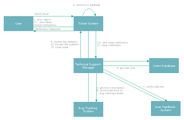
"The most common issue tracking system's design is relatively simple. A database is the main storage repository for all data. The data is managed by the business logic layer of the application. This layer gives the underlying raw data more structure and meaning, preparing it for human consumption. The now human readable data are then presented to the support technician by another software application or web page. The end-user of the issue tracking system can create entirely new issues, read existing issues, add details to existing issues, or resolve an issue. When a user of the system makes a change, the issue tracking system will record the action and who made it, so as to maintain a history of the actions taken. Each user of the system may have issues assigned to them, that is, that user is responsible for the proper resolution of that issue. This is generally presented to the user in a list format. The user may have the option of re-assigning an issue to another user, if needed. For security, an issue tracking system will authenticate its users before allowing access to the systems." [Issue tracking system. Wikipedia]
The UML communication diagram example "Ticket processing system" was created using the ConceptDraw PRO diagramming and vector drawing software extended with the Rapid UML solution from the Software Development area of ConceptDraw Solution Park.
The UML communication diagram example "Ticket processing system" was created using the ConceptDraw PRO diagramming and vector drawing software extended with the Rapid UML solution from the Software Development area of ConceptDraw Solution Park.
UML communication diagram
Network Diagram Software LAN Network Diagrams & Diagrams for LAN Physical Office Network Diagrams


UML Diagram for System

Network Diagrams for Bandwidth Management

- Schematic Digram On Process Of Communication
- UML Tool & UML Diagram Examples | Communication Diagram ...
- Communication network diagram | Telecommunication Network ...
- Communication medium diagram | Network Diagram Examples ...
- Mobile satellite communication network diagram
- Schematic Diagram On Process Communications
- Communication Diagram Example For Online Shopping
- Uml Communication Diagram
- UML 2 4 Process Flow Diagram | Diagramming Software for Design ...
- Draw A Schematic Diagram On Process Of Communication
- UML package diagram - Template | UML communication diagram ...
- Telecommunication Network Diagrams | Design elements ...
- Diagramming Software for Design UML Communication Diagrams ...
- UML communication diagram - Client server access | UML ...
- Communication Diagram
- Tv Communication Diagram
- Communication Diagram Examples
- UML communication diagram - Client server access | Gestures ...
- Satellite telecom network diagram | Mobile satellite communication ...
- Mobile satellite communication network diagram | Personal area ...