Electrical Symbols — Logic Gate Diagram

Electrical Symbols — Maintenance

Electrical Symbols — Analog and Digital Logic

Electrical Symbols — Delay Elements

Electrical Symbols — Lamps, Acoustics, Readouts

Electrical Symbols — Composite Assemblies

Electrical Symbols — Semiconductor Diodes

Electrical Symbols — Resistors

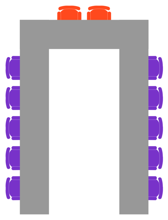
Table Seating Chart Template
Symbol for Pool Table for Floor Plans

Restaurant Floor Plan Software

Building Plans with ConceptDraw DIAGRAM

How to create Cafe Floor Plan Design
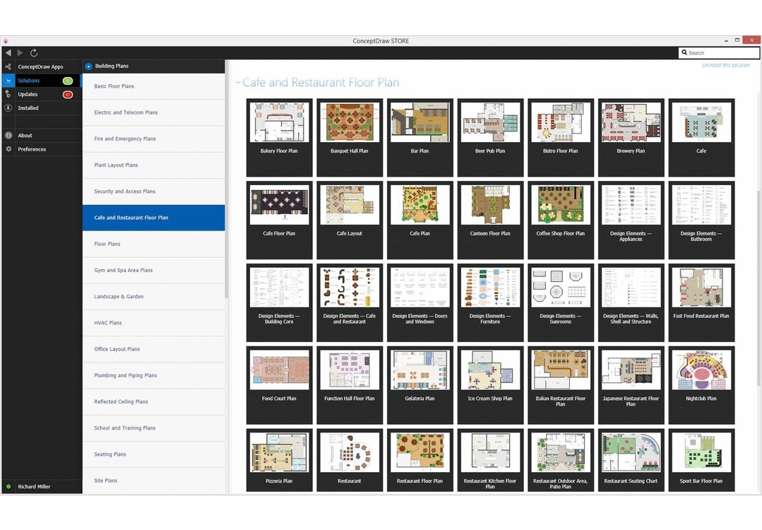
Restaurant Floor Plans Software

Create Floor Plans Easily with ConceptDraw DIAGRAM


- Table Fan Motor Winding Diagram
- Table Fan Motor Wiring Diagram
- Table Fan Wiring Diagram
- Electrical Symbols — Logic Gate Diagram | Basic Table Fan Wiring ...
- Circuit Diagram Of Table Fan Wainding
- Electric Table Fan Circuit Diagram
- Electrical Symbols — Logic Gate Diagram | Ckt Diagram Of A Table ...
- Table Fan Circuit
- Process Flowchart | Table Fan Motor Circuit Diagram
- Electrical Symbols — Logic Gate Diagram | Table Fan Winding ...
- Table Fan Electrical Circuit Diagram
- Electrical Symbols — Logic Gate Diagram | Table Fan Electric Wiring
- Table Fan Connection Circuit Diagram
- How To use House Electrical Plan Software | Table Fan Single ...
- Electrical Symbols — Logic Gate Diagram | Table Fan Winding ...
- Electrical Symbols — Composite Assemblies | Table Fan Motor Wiring
- How To use House Electrical Plan Software | Home Table Fans ...
- Process Flowchart | Table Fan Electrical Symbol
- How To Rewind A Table Fan And Connetion Diagram
- Process Flowchart | Electrical Symbols — Logic Gate Diagram ...