Electrical Symbols, Electrical Diagram Symbols
How to create Electrical Diagram? It’s very easy! All you need is a powerful software. It wasn’t so easy to create Electrical Symbols and Electrical Diagram as it is now with electrical diagram symbols offered by the libraries of Electrical Engineering Solution from the Industrial Engineering Area at the ConceptDraw Solution Park.This solution provides 26 libraries which contain 926 electrical symbols from electrical engineering: Analog and Digital Logic, Composite Assemblies, Delay Elements, Electrical Circuits, Electron Tubes, IGFET, Inductors, Integrated Circuit, Lamps, Acoustics, Readouts, Logic Gate Diagram, MOSFET, Maintenance, Power Sources, Qualifying, Resistors, Rotating Equipment, Semiconductor Diodes, Semiconductors, Stations, Switches and Relays, Terminals and Connectors, Thermo, Transformers and Windings, Transistors, Transmission Paths,VHF UHF SHF.
Electrical Symbols — Electrical Circuits
A circuit diagram or wiring diagram uses symbols to represent parts of a circuit.Electrical and electronic circuits can be complicated. Making a drawing of the connections to all the component parts in the circuit's load makes it easier to understand how circuit components are connected. Drawings for electronic circuits are called "circuit diagrams". Drawings for electrical circuits are called "wiring diagrams".
26 libraries of the Electrical Engineering Solution of ConceptDraw DIAGRAM make your electrical diagramming simple, efficient, and effective. You can simply and quickly drop the ready-to-use objects from libraries into your document to create the electrical diagram.
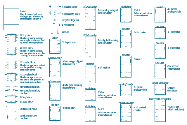
The vector stencils library "Integrated circuit" contains 43 component symbols: transducers, rotary devices, converters, registers, analog switches, counters, registers, decoders, and multiplex transmitters.
"An integrated circuit or monolithic integrated circuit (also referred to as an IC, a chip, or a microchip) is a set of electronic circuits on one small plate ("chip") of semiconductor material, normally silicon. This can be made much smaller than a discrete circuit made from independent components.
Integrated circuits are used in virtually all electronic equipment today and have revolutionized the world of electronics. Computers, mobile phones, and other digital home appliances are now inextricable parts of the structure of modern societies, made possible by the low cost of producing integrated circuits." [Integrated circuit. Wikipedia]
The symbols example "Design elements - Integrated circuit" was drawn using the ConceptDraw PRO diagramming and vector drawing software extended with the Electrical Engineering solution from the Engineering area of ConceptDraw Solution Park.
Electrical Symbols — Integrated Circuit
An integrated circuit (also referred to as an IC, a chip, or a microchip) is a set of electronic circuits on one small plate ("chip") of semiconductor material, normally silicon. This can be made much smaller than a discrete circuit made from independent electronic components. ICs can be made very compact, having up to several billion transistors and other electronic components in an area the size of a human fingernail.26 libraries of the Electrical Engineering Solution of ConceptDraw DIAGRAM make your electrical diagramming simple, efficient, and effective. You can simply and quickly drop the ready-to-use objects from libraries into your document to create the electrical diagram.
Electrical Drawing Software and Electrical Symbols
ConceptDraw DIAGRAM is a powerful software for creating professional looking electrical circuits quick and easy. For this purpose you can use the Electrical Engineering solution from the "Engineering" area of ConceptDraw Solution Park.Electrical Drawing Software provides the 26 stencils libraries of ready-to-use predesigned vector electrical symbols, templates and samples that make your electrical drawing quick, easy and effective.
Circuits and Logic Diagram Software
ConceptDraw DIAGRAM provides Electrical Engineering solution from the Industrial Engineering Area of ConceptDraw Solution Park.Electrical Engineering solution helps you create quick and easy: Electrical schematics, Digital and analog logic designs, Circuit and wiring schematics and diagrams, Power systems diagrams, Maintenance and repair diagrams, Circuit board and amplifier diagrams, Integrated circuit schematics.
Wiring Diagrams with ConceptDraw DIAGRAM
A wiring diagram is a comprehensive diagram of each electrical circuit system showing all the connectors, wiring, terminal boards, signal connections (buses) between the devices and electrical or electronic components of the circuit. It also identifies the wires by wire numbers or colour coding. Wiring diagrams are necessary to troubleshoot and fix electrical or electronic circuits.
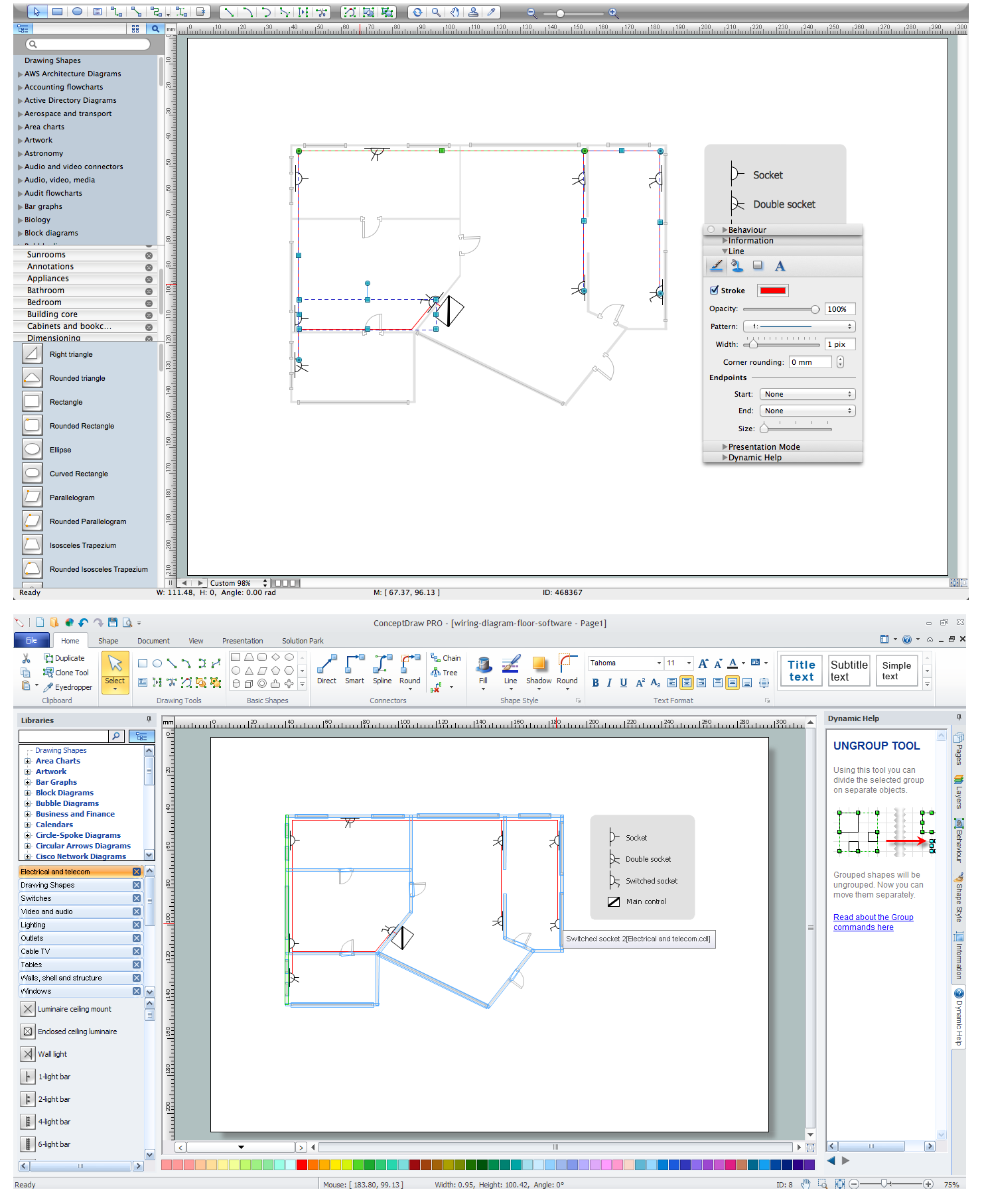
Wiring Diagram Floor Software
This sample shows diagram of the electrical wiring of the apartment. You can see the arrangement of the sockets and the main control on this diagram. The electrical diagram is the important part of the architectural project.Using the predesigned objects, templates and samples of the Electrical Engineering solution for ConceptDraw DIAGRAM you can create your own professional electrical diagrams, wiring diagrams quick and easy.
Electrical Diagram Software
Electrical Diagram Software will assist you in drawing your electrical diagrams with minimal effort and makes it very easy for beginners. Electrical symbols and smart connectors help present your electrical drawings, electrical schematic, wiring diagrams and blue prints.Electrical Engineering Solution for ConceptDraw DIAGRAM provides the 26 stencils libraries of ready-to-use predesigned vector symbols, templates and samples that make your electrical drawing quick, easy and effective.

Electrical Symbols — Power Sources
A voltage source is a two terminal device which can maintain a fixed voltage. An ideal voltage source can maintain the fixed voltage independent of the load resistance or the output current. However, a real-world voltage source cannot supply unlimited current. A voltage source is the dual of a current source. Real-world sources of electrical energy, such as batteries, generators, and power systems, can be modeled for analysis purposes as a combination of an ideal voltage source and additional combinations of impedance elements.26 libraries of the Electrical Engineering Solution of ConceptDraw DIAGRAM make your electrical diagramming simple, efficient, and effective. You can simply and quickly drop the ready-to-use objects from libraries into your document to create the electrical diagram.
Electrical Symbols — Lamps, Acoustics, Readouts
Wiring and circuit diagrams use special symbols recognized by everyone who uses the drawings. The symbols on the drawings show how components like resistors, capacitors, inductors, switches, lamps, acoustic devices, measuring devices and other electrical and electronic components are connected together.26 libraries of the Electrical Engineering Solution of ConceptDraw DIAGRAM make your electrical diagramming simple, efficient, and effective. You can simply and quickly drop the ready-to-use objects from libraries into your document to create the electrical diagram.
"A hydraulic circuit is a system comprising an interconnected set of discrete components that transport liquid. The purpose of this system may be to control where fluid flows (as in a network of tubes of coolant in a thermodynamic system) or to control fluid pressure (as in hydraulic amplifiers).
... hydraulic circuit theory works best when the elements (passive component such as pipes or transmission lines or active components such as power packs or pumps) are discrete and linear. This usually means that hydraulic circuit analysis works best for long, thin tubes with discrete pumps, as found in chemical process flow systems or microscale devices." [Hydraulic circuit. Wikipedia]
The engineering drawing example "Hydraulic circuits" was redrawn using ConceptDraw PRO diagramming and vector drawing software from the Wikimedia Commons file: Hydraulic circuits.png.
[commons.wikimedia.org/ wiki/ File:Hydraulic_ circuits.png]
This file is licensed under the Creative Commons Attribution-Share Alike 3.0 Unported license.
[creativecommons.org/ licenses/ by-sa/ 3.0/ deed.en]
The engineering drawing example "Hydraulic circuits" is included in the Mechanical Engineering solution from the Engineering area of ConceptDraw Solution Park.
Electrical Diagram
Electrical Diagram is a visual graphical representation of an electrical circuit. ConceptDraw DIAGRAM diagramming and vector drawing software supplied with unique Electrical Engineering Solution from the Industrial Engineering Area will help you design Electrical Diagram of any complexity without efforts.Electrical Design Software
ConceptDraw DIAGRAM is a powerful electrical design software. The Electrical Engineering solution from the Engineering area of ConceptDraw Solution Park allows you easy, quick and effective draw the professional looking electrical, circuit and wiring diagrams and schemes, maintenance and repair diagrams for electronics and electrical engineering, and many other types of diagrams.Electrical Symbols — VHF UHF SHF
Ultra high frequency (UHF) is the ITU designation for radio frequencies in the range between 300 MHz and 3 GHz, also known as the decimetre band as the wavelengths range from one meter to one decimetre. Radio waves with frequencies above the UHF band fall into the SHF (super-high frequency) or microwave frequency range. Lower frequency signals fall into the VHF (very high frequency) or lower bands. UHF radio waves propagate mainly by line of sight; they are blocked by hills and large buildings although the transmission through building walls is strong enough for indoor reception. They are used for television broadcasting, cell phones, satellite communication including GPS, personal radio services including Wi-Fi and Bluetooth, walkie-talkies, cordless phones, and numerous other applications.26 libraries of the Electrical Engineering Solution of ConceptDraw DIAGRAM make your electrical diagramming simple, efficient, and effective. You can simply and quickly drop the ready-to-use objects from libraries into your document to create the electrical diagram.
- Symbol Of The Elements Of Electronic Component Used In Circuit
- Circuit Components
- Active Components In A Hydraulic Circuit
- Circuit Components And Symbols
- Electrical Engineering Drawing Circuit Components
- Circuit Symbols
- Electronic Component
- Electrical Circuit Component
- Vacuum Circuit Breaker Symbol
- The Depiction Of Electric Circuit By Symbols Is Called
- Different Symbols Of Electrical Components
- Components And Symbols Of Transducers
- Electric Circuit Components And Their Symbol And Their Task
- Component Of Electric Circuit Pdf
- Components Of An Integrated Circuit
- The Symbol For Circuit Breaker Used In Wiring Circuit Diagram
- Practical Circuit Component
- Hydraulic Circuit Symbol Components
- Electronic Components Symbols And Functions Pdf
- Process Flowchart | Cisco Design | Network Components | Draw ...
- ERD | Entity Relationship Diagrams, ERD Software for Mac and Win
- Flowchart | Basic Flowchart Symbols and Meaning
- Flowchart | Flowchart Design - Symbols, Shapes, Stencils and Icons
- Flowchart | Flow Chart Symbols
- Electrical | Electrical Drawing - Wiring and Circuits Schematics
- Flowchart | Common Flowchart Symbols