Data structure diagram with ConceptDraw DIAGRAM

Software and Database Design with ConceptDraw DIAGRAM

Data Flow Diagram Examples

UML Use Case Diagram Example. Social Networking Sites Project

Online Diagram Tool
Martin ERD Diagram

Data modeling with ConceptDraw DIAGRAM

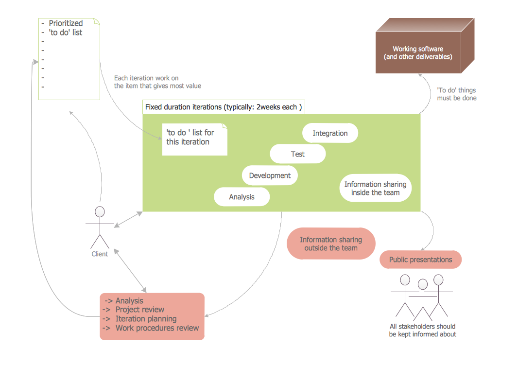
Software Diagram Templates
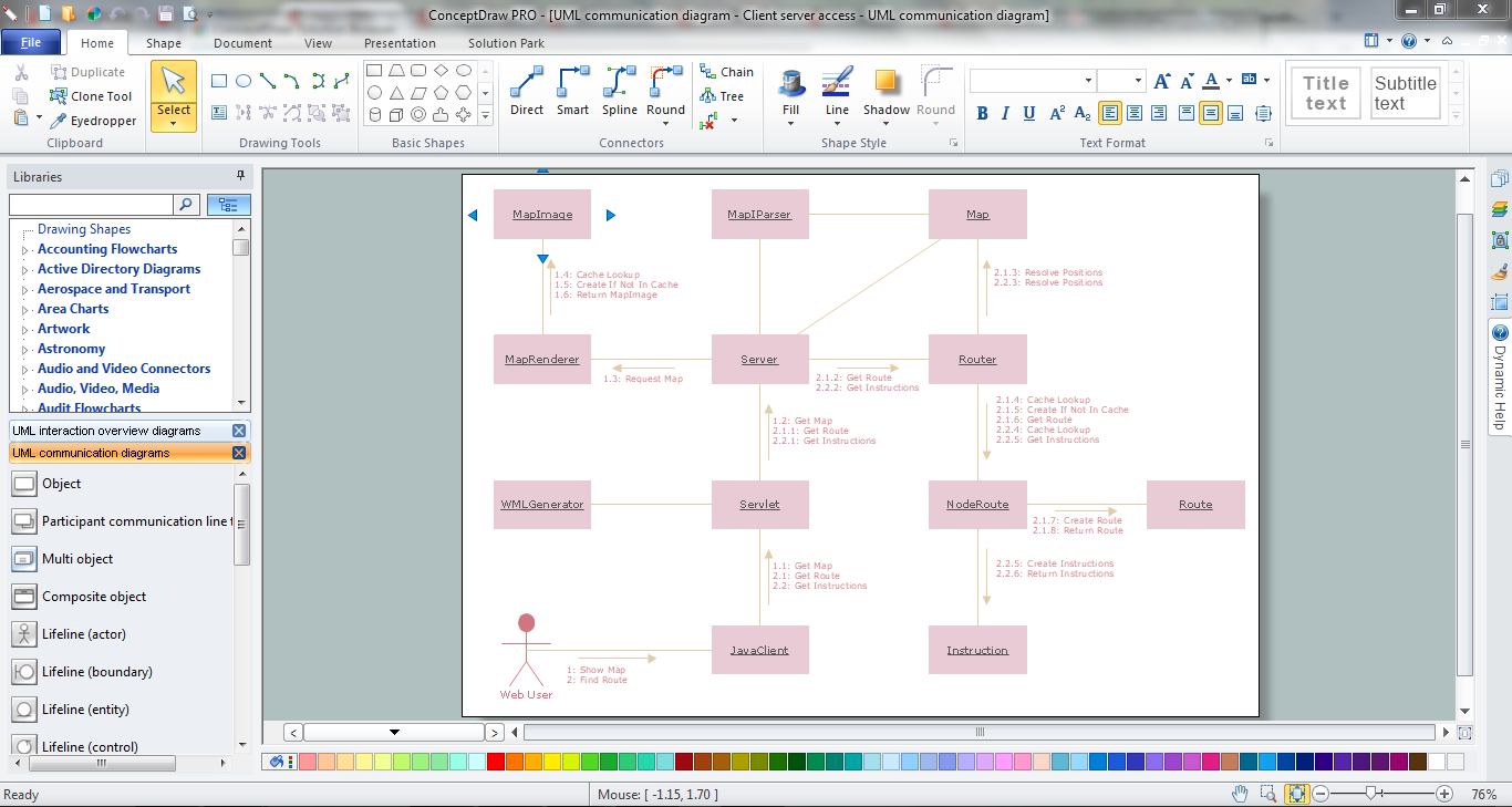
Diagramming Software for UML Composite Structure Diagrams


Jacobson Use Cases Diagram

How to Create a Social Media DFD Flowchart

Software Diagram Examples and Templates

ConceptDraw Arrows10 Technology

Entity Relationship Diagram Software
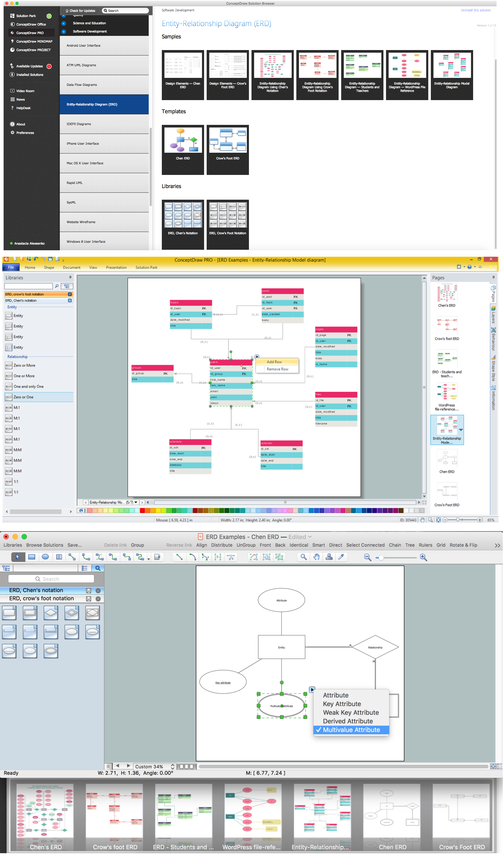
ERD Symbols and Meanings


- Convert Dfd To Erd
- ConceptDraw PRO ER Diagram Tool | DFD Library System | Entity ...
- Entity-Relationship Diagram ( ERD ) | Data Flow Diagrams ...
- UML Diagram | Entity Relationship Diagram Symbols | Diagramming ...
- Data Flow Diagrams
- Yourdon and Coad Diagram | ConceptDraw PRO ER Diagram Tool ...
- Dataflow Diagram Of Bus Ticketing System
- Data Flow Diagrams ( DFD ) | Computer Network Diagrams | Total ...
- Difference Between Dfd And Erd In Software Engineering
- Data Flow Diagrams | Example of DFD for Online Store ( Data Flow ...
- Example of DFD for Online Store ( Data Flow Diagram ) DFD ...
- Entity-Relationship Diagram ( ERD ) | UML Use Case Diagram ...
- How to Create a Social Media DFD Flowchart | UML Use Case ...
- Similarities Between Entity Relationship Diagram And Data Flow
- Entity Relationship Diagram Symbols | Basic Flowchart Symbols and ...
- Entity Relationship Diagram - ERD - Software for Design Crows Foot ...
- Entity Relationship Diagram Data Model
- Entity Relationship Diagram - ERD - Software for Design Crows Foot ...
- Data Flow Diagrams ( DFD ) | DFD Library System | Process ...
- UML use case diagram - Banking system | ConceptDraw PRO ER ...