Network Topologies


Network Diagram Software LAN Network Diagrams & Diagrams for LAN Physical Office Network Diagrams


ConceptDraw PRO Network Diagram Tool

Local network area. Computer and Network Examples

Network Glossary Definition

 Network Layout Floor Plans
Network Layout Floor Plans solution extends ConceptDraw PRO software functionality with powerful tools for quick and efficient documentation the network equipment and displaying its location on the professionally designed Network Layout Floor Plans. Never before creation of Network Layout Floor Plans, Network Communication Plans, Network Topologies Plans and Network Topology Maps was not so easy, convenient and fast as with predesigned templates, samples, examples and comprehensive set of vector design elements included to the Network Layout Floor Plans solution. All listed types of plans will be a good support for the future correct cabling and installation of network equipment.
 Computer and Networks Area
The solutions from Computer and Networks Area of ConceptDraw Solution Park collect samples, templates and vector stencils libraries for drawing computer and network diagrams, schemes and technical drawings.
Network wiring cable. Computer and Network Examples

The design elements library "Cable TV" contains 64 symbols of CATV network equipment.
"Cable television is a system of distributing television programs to subscribers via radio frequency (RF) signals transmitted through coaxial cables or light pulses through fiber-optic cables. This contrasts with traditional broadcast television (terrestrial television) in which the television signal is transmitted over the air by radio waves and received by a television antenna attached to the television. FM radio programming, high-speed Internet, telephone service, and similar non-television services may also be provided through these cables.
The abbreviation CATV is often used for cable television." [Cable television. Wikipedia]
Use the shapes library "Cable TV" to draw CATV system design floor plans, network topology diagrams, wiring diagrams and cabling layout schemes using the ConceptDraw PRO diagramming and vector drawing software.
The vector stencils library "Cable TV" is included in the Electric and Telecom Plans solution from the Building Plans area of ConceptDraw Solution Park.
Cable TV symbols
.png--diagram-flowchart-example.png)
Storage area networks (SAN). Computer and Network Examples
. Computer and Network Examples")
The vector stencils library "Network layout floorplan" contain 34 symbol icons for drawing computer network floor plans, communication equipment layouts, and structured cabling diagrams.
"Structured cabling is building or campus telecommunications cabling infrastructure that consists of a number of standardized smaller elements (hence structured) called subsystems. ...
Structured cabling design and installation is governed by a set of standards that specify wiring data centers, offices, and apartment buildings for data or voice communications using various kinds of cable, most commonly category 5e (CAT-5e), category 6 (CAT-6), and fibre optic cabling and modular connectors. These standards define how to lay the cabling in various topologies in order to meet the needs of the customer, typically using a central patch panel (which is normally 19 inch rack-mounted), from where each modular connection can be used as needed. Each outlet is then patched into a network switch (normally also rack-mounted) for network use or into an IP or PBX (private branch exchange) telephone system patch panel." [Structured cabling. Wikipedia]
The design elements example "Network layout floorplan - Vector stencils library" was created using the ConceptDraw PRO diagramming and vector drawing software extended with the Network Layout Floor Plans solution from the Computer and Networks area of ConceptDraw Solution Park.
PC

Scanner

Switch

Router

Modem

Hub

Rack Mount

Printer

Floor Mounted Outlet

Single Outlet

Duplex Outlet

Direct bus cable

Tops or bottoms bus cable

Side to side bus cable

Multi-tree bus cable

Bottom to side bus cable

Sides bus cable

Door

Door, threshold

Door, stop

Door, stop, threshold

Door, frame

Door, frame, threshold

Door, frame, stop

Door, frame, stop, threshold

Window

Window, sill

Window, sash

Window, sash, sill

Window, frame

Window, frame, sill

Window, frame, sash

Window, frame, sash, sill

The vector stencils library "Network layout floorplan" contain 34 symbol icons for drawing computer network floor plans and communication equipment and cabling layouts.
"Networking hardware may also be known as network equipment or computer networking devices. Units which are the last receiver or generate data are called hosts or data terminal equipment.
All these terms refer to devices facilitating the use of a computer network. Specifically, they mediate data in a computer network. ...
Typically, networking hardware includes gateways, routers, network bridges, switches, hubs, and repeaters. But it also includes hybrid network devices such as multilayer switches, protocol converters, bridge routers, proxy servers, firewalls, network address translators, multiplexers, network interface controllers, wireless network interface controllers, modems, ISDN terminal adapters, line drivers, wireless access points, networking cables and other related hardware.
The most common kind of networking hardware today is a copper-based Ethernet adapter because of its standard inclusion on most modern computer systems. Wireless networking has, however, become increasingly popular, especially for portable and handheld devices.
Other hardware prevalent in computer networking includes data center equipment (such as file servers, database servers and storage areas), network services (such as DNS, DHCP, email, etc.) as well as devices which assure content delivery." [Networking hardware. Wikipedia]
The shapes example "Design elements - Network layout floorplan" was created using the ConceptDraw PRO diagramming and vector drawing software extended with the Network Layout Floor Plans solution from the Computer and Networks area of ConceptDraw Solution Park.
Network layout floor plan symbols

How To use House Electrical Plan Software


The vector stencils library "Cable TV" contains 64 symbols of cable TV network equipment.
Use these shapes for drawing CATV system design floor plans, network topology diagrams, wiring diagrams and cabling layout schemes in the ConceptDraw PRO diagramming and vector drawing software.
The vector stencils library "Cable TV" is included in the Electric and Telecom Plans solution from the Building Plans area of ConceptDraw Solution Park.
Output Directional Tap 1

Output Directional Tap 2

Output Directional Tap 3

Output Directional Tap 4

Output Directional Tap 5

2-way Splitter

3-way Splitter

4-way Splitter

AC Power Block

Bond

Down Guy

Building Guy and Anchor

Rock Guy with Anchor

Down Guy with Anchor

Pole-to-Pole Guy

Sidewalk Down Guy with Anchor

Sidewalk Down Guy

Slack Span Messenger Wire

Tensioned Messenger Wire w/out cable

Tensioned Messenger Wire

Ground

Joint Usage (Power & Telephone Pole)
-cable-tv---vector-stencils-library.png--diagram-flowchart-example.png)
Joint Usgae Pole with Transformer

Strut

Tree Guy with Anchor

Push Brace (smaller pole in actual relative position)
-cable-tv---vector-stencils-library.png--diagram-flowchart-example.png)
Extension Arm

Built CATV Pole

Proposed CATV Pole

Directional Tap 1

Directional Tap 2

Manhole

Telephone Pole

Riser Pole

Vault Handheld

Fixed Equalizer

Fixed Flat Attenuators

Other Supporting Structures

Pedestal - Underground Routing

Power Pole

Direct Buried Underground Routing

Duct Line Underground Routing

Line Terminations

2-Way Optical Splice Location

3-Way Optical Splice Location

4-Way Optical Splice Location

> 4-Way Optical Splice Location

Optical Amplifier

Cable AC Power Combiner

Optical Fiber Cable

Optical Connector

Wavelength Demultiplexer

Wavelength Multiplexer

Optical Transmitter

Optical Transmitter

Optical Node

Optical Splitter

Headend (Signal Processing)
-cable-tv---vector-stencils-library.png--diagram-flowchart-example.png)
Node

Primary Hub

Secondary Hub

Coaxial Splice

Power Supply

Variable Equalizer

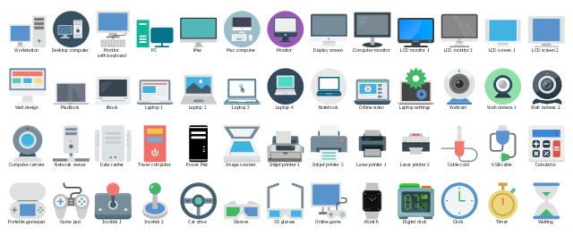
The vector stencils library "Computers" contains 52 computer hardware icons.
Use it to design your audio, video and multimedia illustrations, presentations, web pages and infographics with ConceptDraw PRO diagramming and vector drawing software.
"Computer hardware (or simply hardware in computing contexts) is the collection of physical elements that constitutes a computer system. Computer hardware is the physical parts or components of a computer, such as the monitor, keyboard, computer data storage, hard disk drive (HDD), graphic cards, sound cards, memory (RAM), motherboard, and so on, all of which are tangible physical objects." [Computer hardware. Wikipedia]
The clipart example "Computers" is included in the Audio, Video, Media solution from the Illustrations area of ConceptDraw Solution Park.
Multimedia clipart
The vector stencils library "Cisco network topology" contains 89 symbols of Cisco network devices and design elements for drawing computer network topology diagrams.
"There are two basic categories of network topologies:
(1) Physical topologies,
(2) Logical topologies.
The shape of the cabling layout used to link devices is called the physical topology of the network. This refers to the layout of cabling, the locations of nodes, and the interconnections between the nodes and the cabling. The physical topology of a network is determined by the capabilities of the network access devices and media, the level of control or fault tolerance desired, and the cost associated with cabling or telecommunications circuits.
The logical topology in contrast, is the way that the signals act on the network media, or the way that the data passes through the network from one device to the next without regard to the physical interconnection of the devices." [Network topology. Wikipedia]
The symbols example "Cisco network topology - Vector stencils library" was created using the ConceptDraw PRO diagramming and vector drawing software extended with the Cisco Network Diagrams solution from the Computer and Networks area of ConceptDraw Solution Park.
www.conceptdraw.com/ solution-park/ computer-networks-cisco
Router

Broadband router

Router firewall

Wireless router

Workgroup switch

ATM switch

ISDN switch

Multilayer switch

Protocol translator

Communications server

Transpath

Bridge

Terminal server

Route switch processor

Content engine (cache director)
-cisco-network-topology---vector-stencils-library.png--diagram-flowchart-example.png)
Management engine (ME 1100)
-cisco-network-topology---vector-stencils-library.png--diagram-flowchart-example.png)
Switch processor

ITP

Voice gateway

BBSM

ATA

SIP Proxy server

NetRanger

Cisco 1000

IP

System controller

ACE

Directory server

ADM

Cisco Unity Express

Unity server

Cisco security

CallManager

DSLAM

H.323

CDM (Content Distribution Manager)
-cisco-network-topology---vector-stencils-library.png--diagram-flowchart-example.png)
ICM

Access point

Wireless bridge

Wireless connectivity

Guard

Mobile access router

Carrier Routing System (CRS)
-cisco-network-topology---vector-stencils-library.png--diagram-flowchart-example.png)
Vault

Workstation

PC

Macintosh

Cloud, gold

Cloud, white

Cloud, standard color

Cisco security management

PBX

DPT

Government building

Headquarters, blue

Router in building

Man

Woman

Workgroup switch, subdued

Router, subdued

File server

Firewall, horizontal

Firewall, vertical

Firewall, vertical, subdued

Lock

Key

Lock and key

Car

Truck

File cabinet

Breakout box

Breakout box, blue

Host

Relational database

Modem

BBS (Bulletin Board System)
-cisco-network-topology---vector-stencils-library.png--diagram-flowchart-example.png)
Satellite

Satellite dish

UPS

RPS

MAU

PAD

PAD X.28

Diskette

Contact center

Page icon
Antenna

Antenna, blue

Radio tower

 Security and Access Plans
This solution extends ConceptDraw PRO software with physical security plan, security chart, access chart, security plans, access schemes, access plans , CCTV System Plan samples, templates and libraries of design elements for drawing the Security and Acce
- Ethernet local area network layout floor plan | Network Layout Floor ...
- Network Diagramming with ConceptDraw PRO | Local area network ...
- Network Layout | Ethernet local area network layout floor plan ...
- Local network physical topology floor plan | ConceptDraw PRO ...
- Home area networks (HAN). Computer and Network Examples ...
- ConceptDraw PRO Network Diagram Tool | Wiring Diagrams with ...
- Diagram Physical Topologies | Hotel Network Topology Diagram ...
- Cable Network . Computer and Network Examples | Network ...
- Network Diagramming Software for Design Network Layout ...
- Ethernet local area network layout floor plan | Network Layout Floor ...
- Ethernet local area network layout floor plan | Design elements ...
- Roaming wireless local area network diagram | Network Architecture ...
- Home area network wiring diagram | Network wiring cable ...
- Network Layout Floor Plans | Network Layout | Design elements ...
- Network Layout Floor Plans | Network Layout | Design elements ...
- ConceptDraw PRO Network Diagram Tool | Design elements ...
- ConceptDraw PRO Network Diagram Tool | Network Diagramming ...
- How To use Switches in Network Diagram | Cisco Network Objects ...
- Home area network (HAN) wiring diagram | Design elements - Video ...
- Network Layout Floor Plans | Office wireless network plan | Network ...