"The ideal telecommunication network has the following characteristics: broadband, multi-media, multi-point, multi-rate and economical implementation for a diversity of services (multi-services). The Broadband Integrated Services Digital Network (B-ISDN) intended to provide these characteristics. Asynchronous Transfer Mode (ATM) was promoted as a target technology for meeting these requirements" [Broadband networks. Wikipedia]
"Wireless broadband is technology that provides high-speed wireless Internet access or computer networking access over a wide area. ...
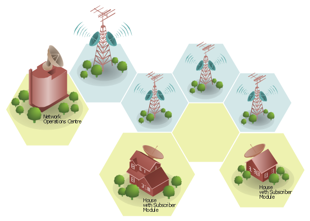
Wireless networks can feature data rates roughly equivalent to some wired networks, such as that of asymmetric digital subscriber line (ADSL) or a cable modem. Wireless networks can also be symmetrical, meaning the same rate in both directions (downstream and upstream), which is most commonly associated with fixed wireless networks. A fixed wireless network link is a stationary terrestrial wireless connection, which can support higher data rates for the same power as mobile or satellite systems.
Few wireless Internet service providers (WISPs) provide download speeds of over 100 Mbit/ s; most broadband wireless access (BWA) services are estimated to have a range of 50 km (31 mi) from a tower. Technologies used include LMDS and MMDS, as well as heavy use of the ISM bands and one particular access technology was standardized by IEEE 802.16, with products known as WiMAX." [Wireless broadband. Wikipedia]
Wireless broadband is technology that provides high-speed wireless Internet access or computer networking access over a wide area. [Wireless broadband. Wikipedia]
This wireless broadband network diagram example was created using the ConceptDraw PRO diagramming and vector drawing software extended with the Telecommunication Network Diagrams solution from the Computer and Networks area of ConceptDraw Solution Park.
"Wireless broadband is technology that provides high-speed wireless Internet access or computer networking access over a wide area. ...
Wireless networks can feature data rates roughly equivalent to some wired networks, such as that of asymmetric digital subscriber line (ADSL) or a cable modem. Wireless networks can also be symmetrical, meaning the same rate in both directions (downstream and upstream), which is most commonly associated with fixed wireless networks. A fixed wireless network link is a stationary terrestrial wireless connection, which can support higher data rates for the same power as mobile or satellite systems.
Few wireless Internet service providers (WISPs) provide download speeds of over 100 Mbit/ s; most broadband wireless access (BWA) services are estimated to have a range of 50 km (31 mi) from a tower. Technologies used include LMDS and MMDS, as well as heavy use of the ISM bands and one particular access technology was standardized by IEEE 802.16, with products known as WiMAX." [Wireless broadband. Wikipedia]
Wireless broadband is technology that provides high-speed wireless Internet access or computer networking access over a wide area. [Wireless broadband. Wikipedia]
This wireless broadband network diagram example was created using the ConceptDraw PRO diagramming and vector drawing software extended with the Telecommunication Network Diagrams solution from the Computer and Networks area of ConceptDraw Solution Park.
Wireless broadband network diagram
ATM Network. Computer and Network Examples


How to Create Cisco Network Diagram

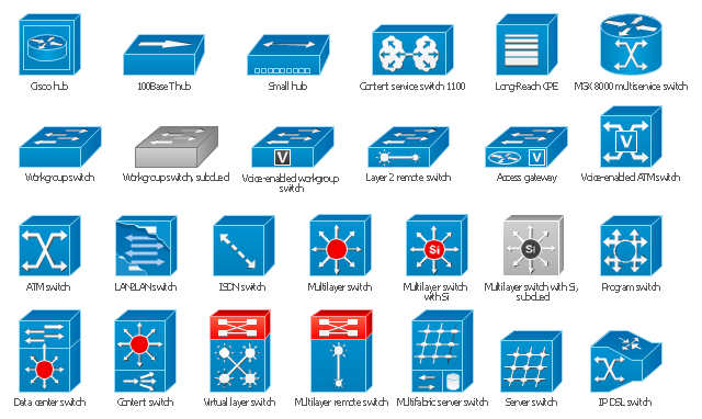
The vector stencils library "Cisco switches and hubs" contains 26 symbols for drawing computer network diagrams using the ConceptDraw PRO diagramming and vector drawing software.
"A network switch (sometimes known as a switching hub) is a computer networking device that is used to connect many devices together on a computer network. A switch is considered more advanced than a hub because a switch will only send a message to the device that needs or requests it, rather than broadcasting the same message out of each of its ports.
A switch is a multi-port network bridge that processes and forwards data at the data link layer (layer 2) of the OSI model. Some switches have additional features, including the ability to route packets. These switches are commonly known as layer-3 or multilayer switches. Switches exist for various types of networks including Fibre Channel, Asynchronous Transfer Mode, InfiniBand, Ethernet and others." [Network switch. Wikipedia]
"An Ethernet hub, active hub, network hub, repeater hub, multiport repeater or hub is a device for connecting multiple Ethernet devices together and making them act as a single network segment. It has multiple input/ output (I/ O) ports, in which a signal introduced at the input of any port appears at the output of every port except the original incoming. A hub works at the physical layer (layer 1) of the OSI model. The device is a form of multiport repeater. Repeater hubs also participate in collision detection, forwarding a jam signal to all ports if it detects a collision.
Some hubs may also come with a BNC and/ or Attachment Unit Interface (AUI) connector to allow connection to legacy 10BASE2 or 10BASE5 network segments." [Ethernet hub. Wikipedia]
The example "Design elements - Cisco switches and hubs" is included in the Cisco Network Diagrams solution from the Computer and Networks area of ConceptDraw Solution Park.
Cisco switches and hubs symbols
The vector stencils library "Computers and network isometric" contains 56 3D clipart images of computer and network devices and equipment for drawing network diagrams.
The clip art example "Computers and network isometric - Vector stencils library" was created using the ConceptDraw PRO diagramming and vector drawing software extended with the Computer and Networks solution from the Computer and Networks area of ConceptDraw Solution Park.
The clip art example "Computers and network isometric - Vector stencils library" was created using the ConceptDraw PRO diagramming and vector drawing software extended with the Computer and Networks solution from the Computer and Networks area of ConceptDraw Solution Park.
Laptop

DDCS

Server

Webcam

Wireless Network Storage

Personal computer

VoIP phone

Fax

Plotter

Mobile phone

Feature phone

Printer

Satellite dish

Satellite antenna

Automatic-tracking satellite dish
Wireless access point

Wireless router

Router

Network switch

Network device

Mobile GPS Terminal

GPS phone

Television antenna

Radio tower

Base station

Satellite

In-vehicle satellite telecommunication

Satellite dishes on ship

Airplane

Internet

Man

Woman

Call-center

Honeycomb

Mountain

Radio waves

Radio waves

Tower block

Office building

House

House

Globe

Wireless security camera

Truck

Tree

Conifer tree

1U hub / switch

2U hub / switch

1U server

2U Server

3U Server

4U Server

Communications satellite

Car

Radio waves

Firewall

Virtual private networks (VPN). Computer and Network Examples
. <br>Computer and Network Examples *")
Communication Network Topology

Campus Area Networks (CAN). Computer and Network Examples
. <br>Computer and Network Examples *")
UML Composite Structure Diagram


Interactive voice response (IVR) networks. Computer and Network Examples
 networks. <br>Computer and Network Examples *")
Storage area networks (SAN). Computer and Network Examples
. <br>Computer and Network Examples *")
Network wiring cable. Computer and Network Examples

Digital Communications Network. Computer and Network Examples

UML Deployment Diagram Example - ATM System UML diagrams

Telecommunications Networks

Calculate the cost of creating or updating a wireless computer network

Diagramming software for Amazon Web Service icon set: Monitoring, Deployment, Management
UML Use Case Diagram Example. Services UML Diagram. ATM system

Network Glossary Definition

Biology Illustration

- Telecommunication Network Diagrams | Network Diagram Software ...
- Image Of Network Topology Of Asynchronous Transfer Mode Atm
- ATM Network . Computer and Network Examples | Network ...
- Computers and network isometric - Vector stencils library
- Wireless broadband network diagram | Telecommunication Network ...
- Wireless broadband network diagram | Network Drawing Software ...
- Wireless broadband network diagram | Forces shaping the ...
- Wireless broadband network diagram | Illustrate the Computer ...
- Wireless broadband network diagram | Pyramid Diagram | Mesh ...
- Wireless broadband network diagram | Trango - Vector stencils ...
- Cisco Network Diagrams | Local area network (LAN). Computer and ...
- Wireless broadband network diagram | Wireless Networks | Draw ...
- Wireless broadband network diagram | Network Diagram Software ...
- Wireless broadband network diagram | Roaming wireless local area ...
- Wireless broadband network diagram | Mobile satellite ...
- Wireless broadband network diagram | Network Protocols | Tranzeo ...
- Wireless broadband network diagram | Mesh Network Topology ...
- Computer network diagram | Wireless broadband network diagram ...
- Office wireless network plan | Wireless Networks | Wireless ...
- Computer network diagram | Computer Network Diagrams | Network ...