Mechanical Drawing Symbols

The vector stencils library "Valve assembly" contains 141 symbols of pressure and flow regulators, flow direction indicators, controls, and symbols to design flow paths of control valves.
Use these valve assembly shapes to design the engineering drawings of hydraulic and pneumatic valve assemblies in fluid power systems.
"Control valves are valves used to control conditions such as flow, pressure, temperature, and liquid level by fully or partially opening or closing in response to signals received from controllers that compare a "setpoint" to a "process variable" whose value is provided by sensors that monitor changes in such conditions.
The opening or closing of control valves is usually done automatically by electrical, hydraulic or pneumatic actuators. Positioners are used to control the opening or closing of the actuator based on electric, or pneumatic signals.
A control valve consists of three main parts in which each part exist in several types and designs: Valve's actuator, Valve's positioner, Valve's body.
" [Control valves. Wikipedia]
The shapes example "" was created using the ConceptDraw PRO diagramming and vector drawing software extended with the Mechanical Engineering solution from the Engineering area of ConceptDraw Solution Park.
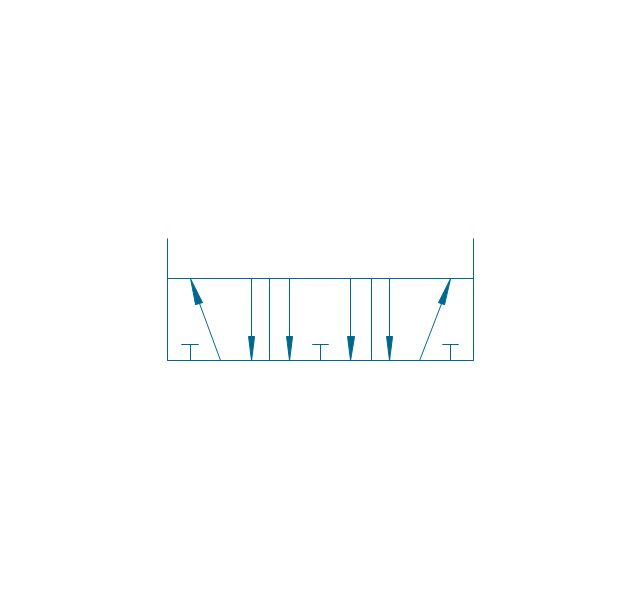
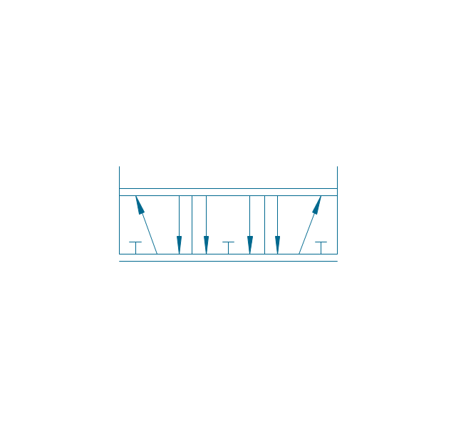
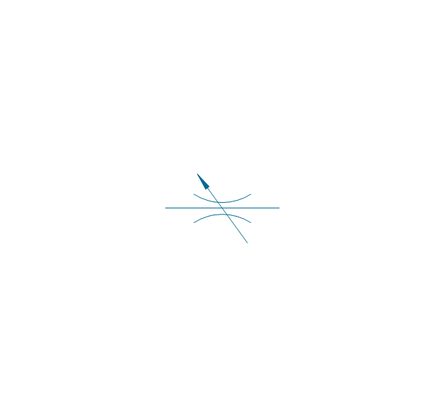
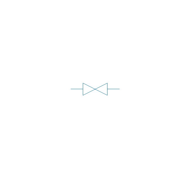
Valve assembly symbols

 Engineering
This solution extends ConceptDraw DIAGRAM.4 with the ability to visualize industrial systems in electronics, electrical, chemical, process, and mechanical engineering.
 Mechanical Engineering
This solution extends ConceptDraw DIAGRAM.9 mechanical drawing software (or later) with samples of mechanical drawing symbols, templates and libraries of design elements, for help when drafting mechanical engineering drawings, or parts, assembly, pneumatic,
Technical Drawing Software

Mechanical Design Software

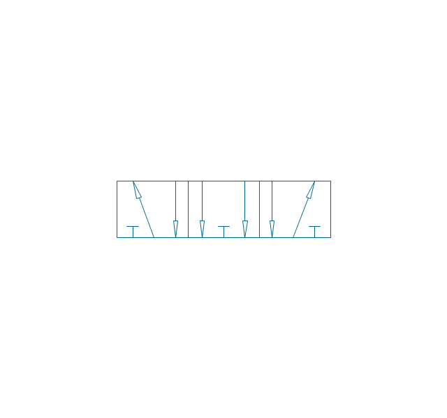
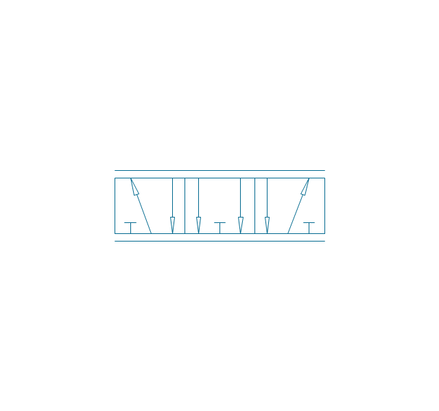
The vector stencils library "Fluid power valves" contains 93 symbols of pre-made hydraulic and pneumatic valves, including directional control valves, flow control valves, pressure control valves, and electrohydraulic and electropneumatic valves.
Use these shapes to design fluid power diagrams in the ConceptDraw PRO diagramming and vector drawing software extended with the Mechanical Engineering solution from the Engineering area of ConceptDraw Solution Park.
www.conceptdraw.com/ solution-park/ engineering-mechanical
Use these shapes to design fluid power diagrams in the ConceptDraw PRO diagramming and vector drawing software extended with the Mechanical Engineering solution from the Engineering area of ConceptDraw Solution Park.
www.conceptdraw.com/ solution-park/ engineering-mechanical
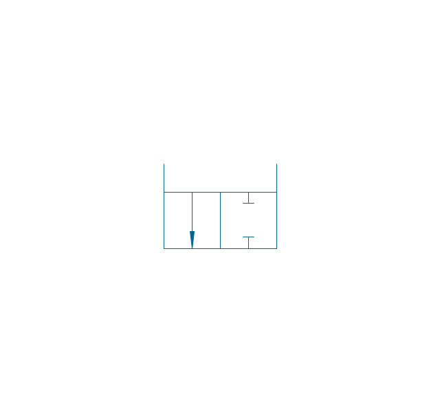
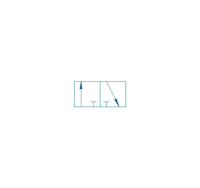
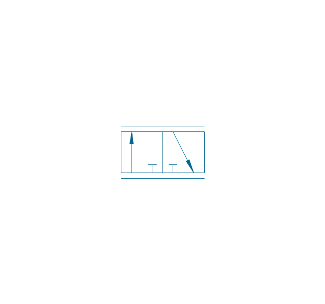
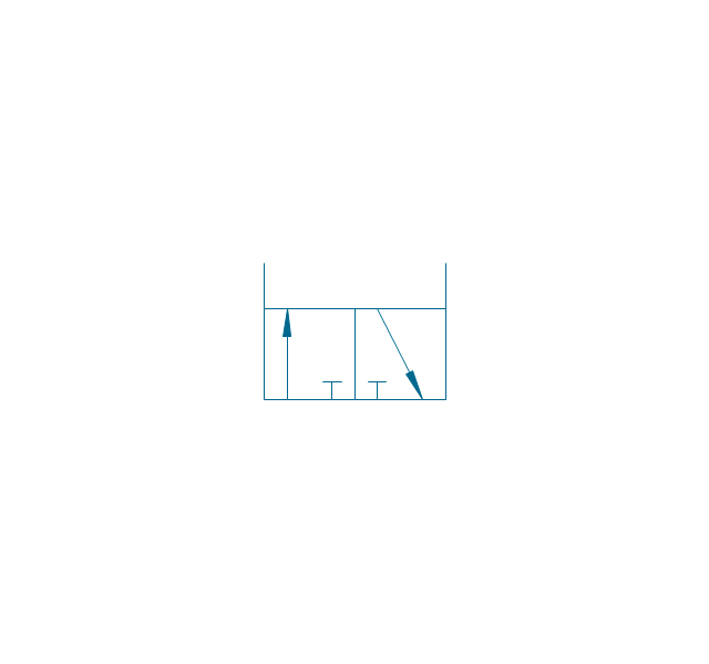
2/2 valve, pneum., finite positions

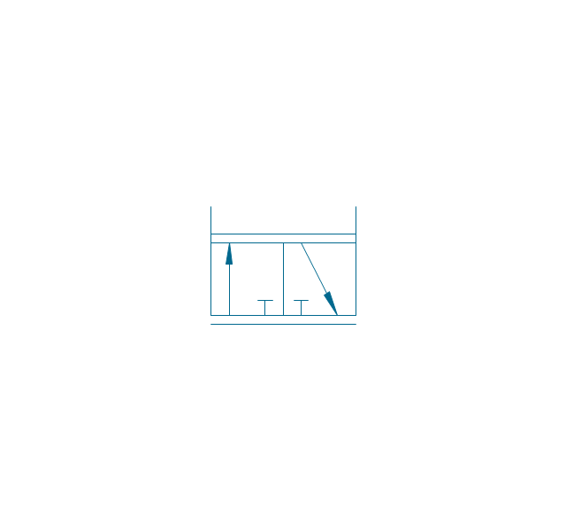
2/2 valve, pneum., infinite positions
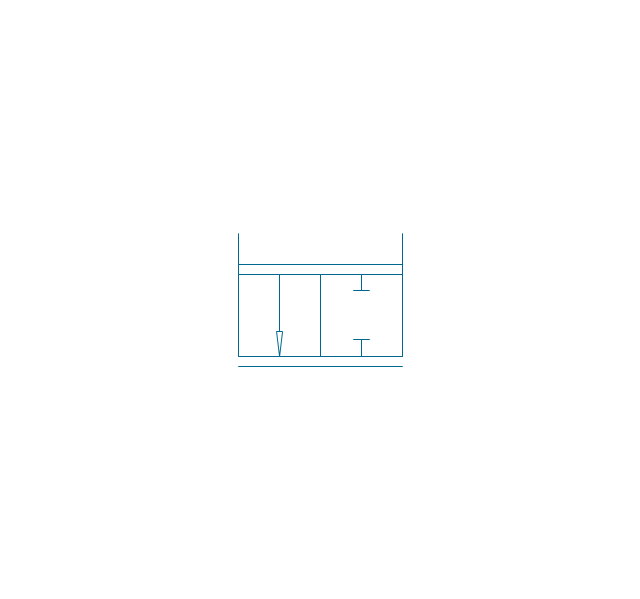
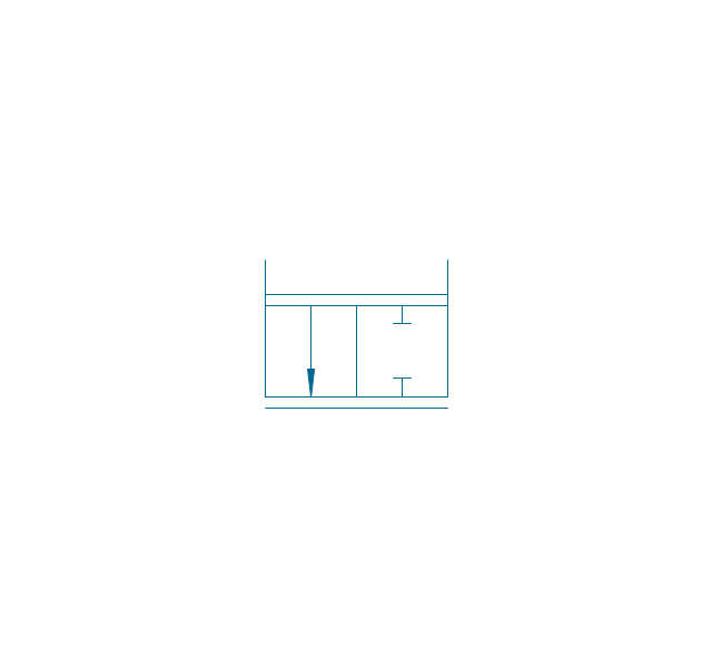
2/2 valve, pneum., ext., fin. pos.
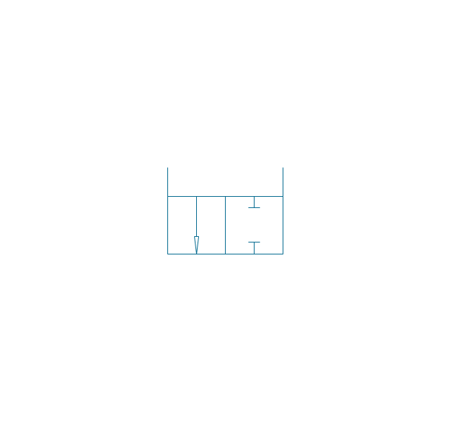
2/2 valve, pneum., ext., infin. pos.
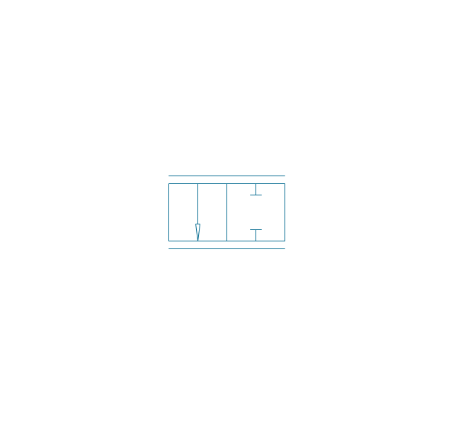
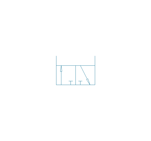
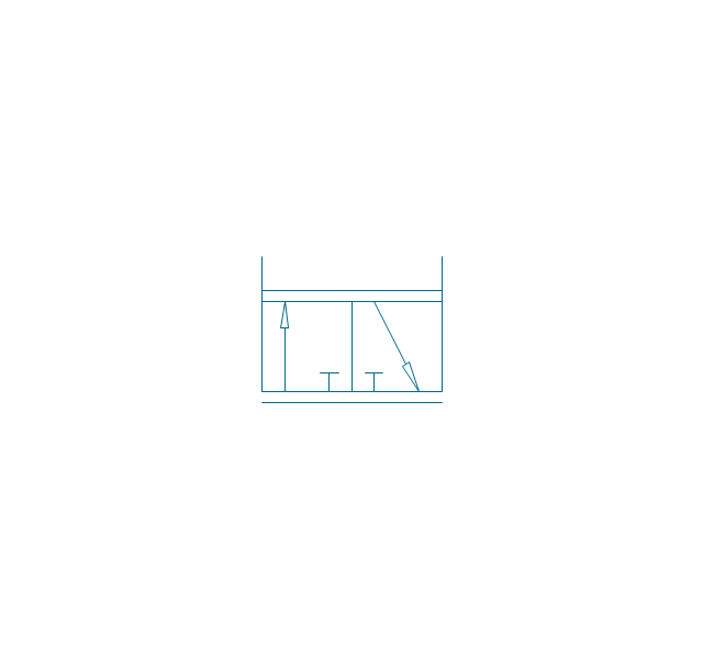
2/2 valve, hydr., finite positions
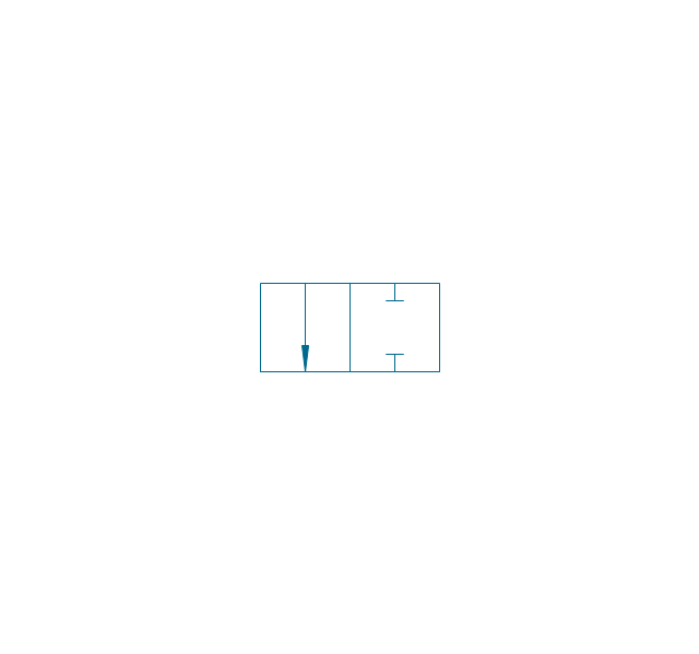
2/2 valve, hydr., infinite positions

2/2 valve, hydr., ext., fin. pos.
2/2 valve, hydr., ext., infin. pos.
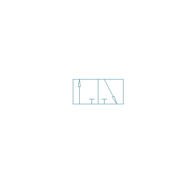
3/2 valve, pneum., finite positions
3/2 valve, pneum., infinite positions
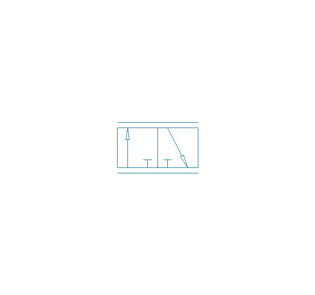
3/2 valve, pneum., ext., fin. pos.
3/2 valve, pneum., ext., infin. pos.
3/2 valve, hydr., finite positions
3/2 valve, hydr., infinite positions
3/2 valve, hydr., ext., fin. pos.
3/2 valve, hydr., ext., infin. pos.
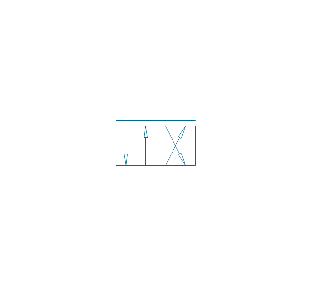
4/2 valve, pneum., finite positions

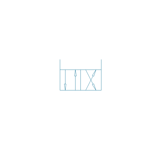
4/2 valve, pneum., infinite positions
4/2 valve, pneum., ext., fin. pos.
4/2 valve, pneum., ext., infin. pos.
4/2 valve, hydr., finite positions

4/2 valve, hydr., infinite positions

4/2 valve, hydr., ext., fin. pos.

4/2 valve, hydr., ext., infin. pos.
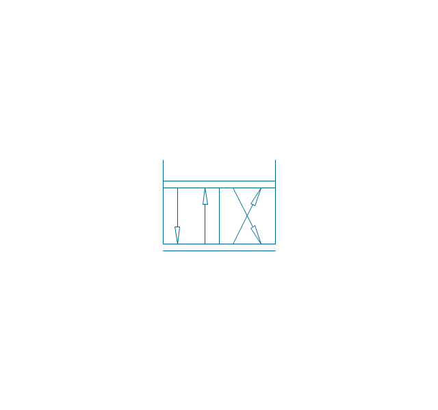
5/2 valve, pneum., finite positions

5/2 valve, pneum., infinite positions
5/2 valve, pneum., ext., fin. pos.

5/2 valve, pneum., ext., infin. pos.

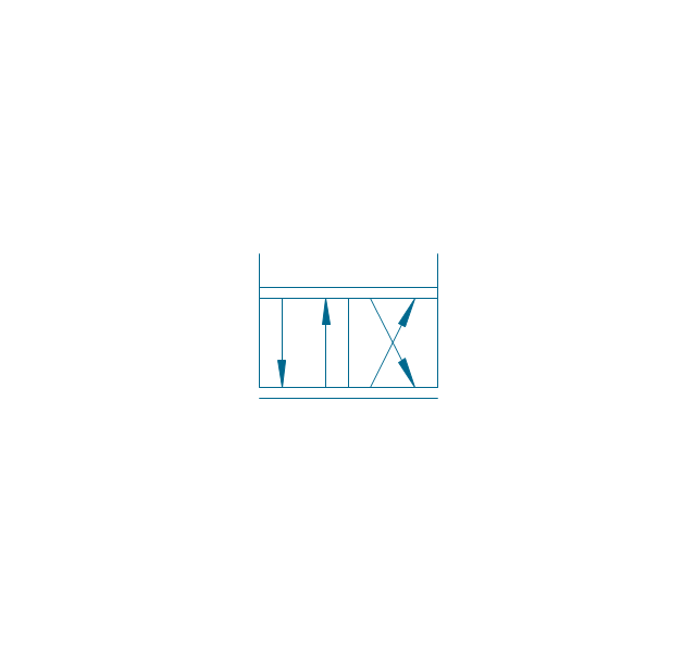
5/2 valve, hydr., finite positions

5/2 valve, hydr., infinite positions

5/2 valve, hydr., ext., fin. pos.
5/2 valve, hydr., ext., infin. pos.
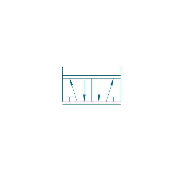
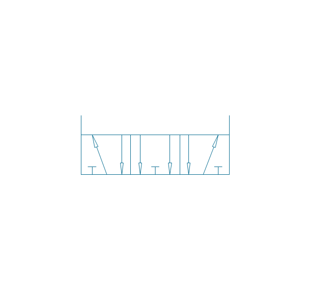
4/3 valve, pneum., finite positions

4/3 valve, pneum., infinite positions

4/3 valve, pneum., ext., fin. pos.

4/3 valve, pneum., ext., infin. pos.
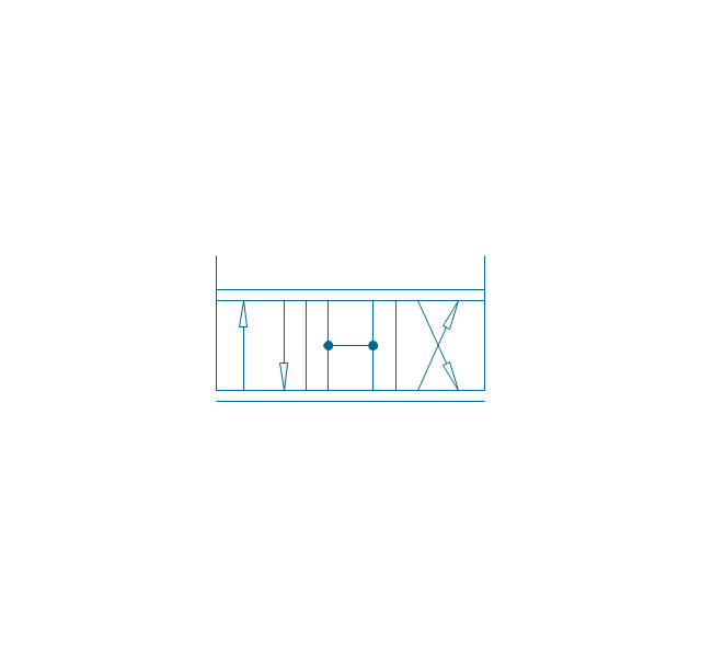
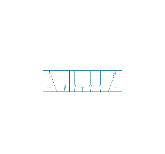
4/3 valve, hydr., finite positions

4/3 valve, hydr., infinite positions

4/3 valve, hydr., ext., fin. pos.

4/3 valve, hydr., ext., infin. pos.

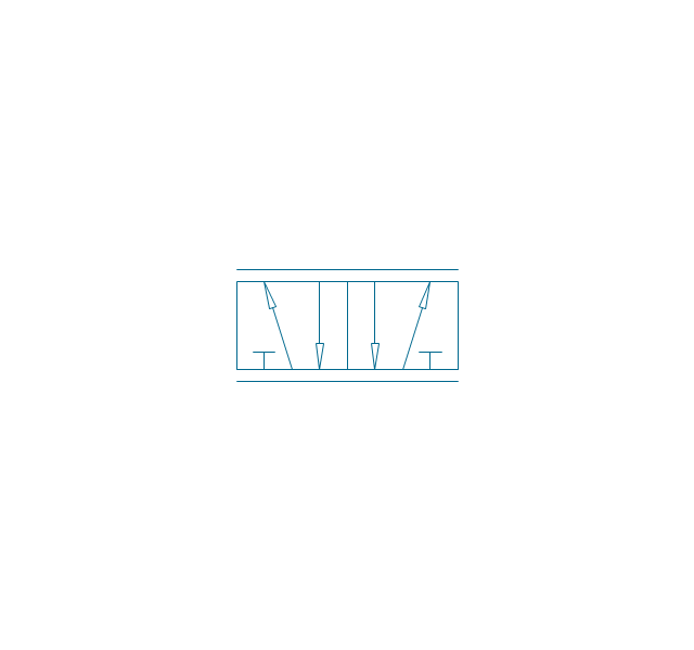
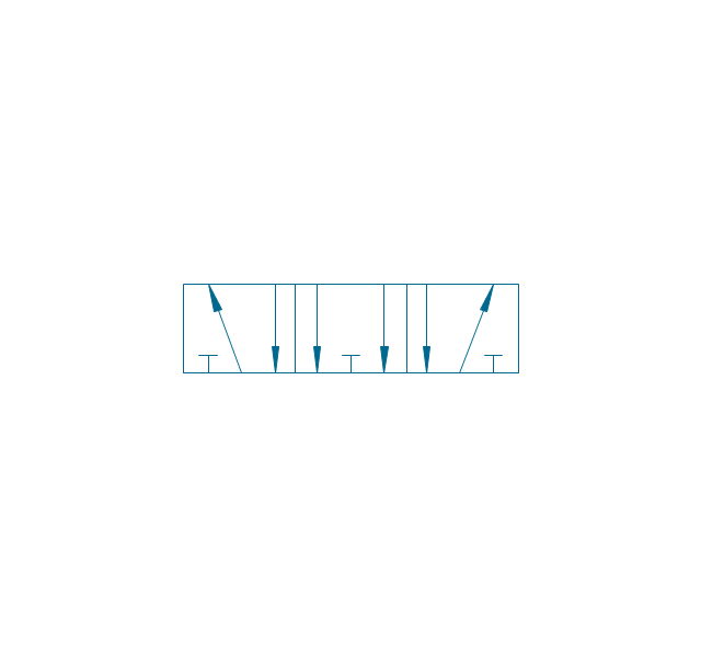
5/3 valve, pneum., finite positions
5/3 valve, pneum., infinite positions
5/3 valve, pneum., ext., fin. pos.
5/3 valve, pneum., ext., infin. pos.
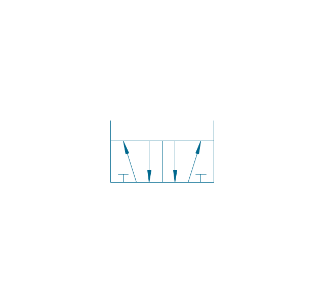
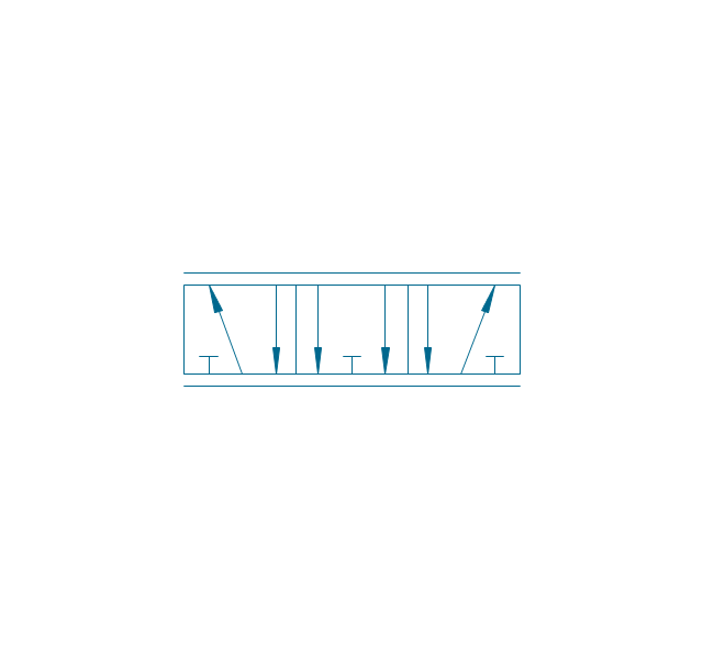
5/3 valve, hydr., finite positions
5/3 valve, hydr., infinite positions
5/3 valve, hydr., ext., fin. pos.
5/3 valve, hydr., ext., infin. pos.
Restrictor valve

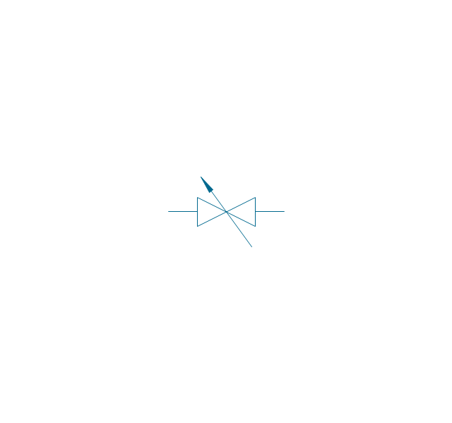
Restrictor valve, adjustable
Gate-valve, norm. open
Gate-valve, norm. open, adj.
Gate-valve, norm. closed

Gate-valve, norm. closed, adj.

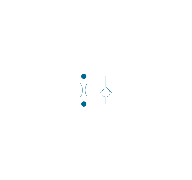
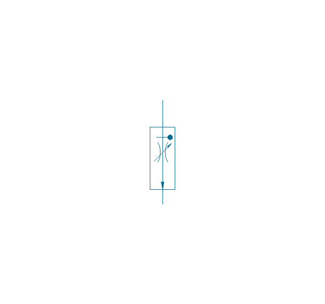
One-way restrictor
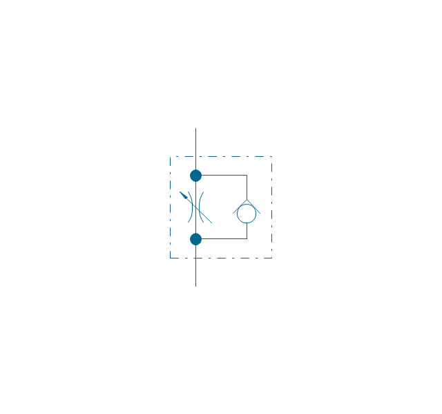
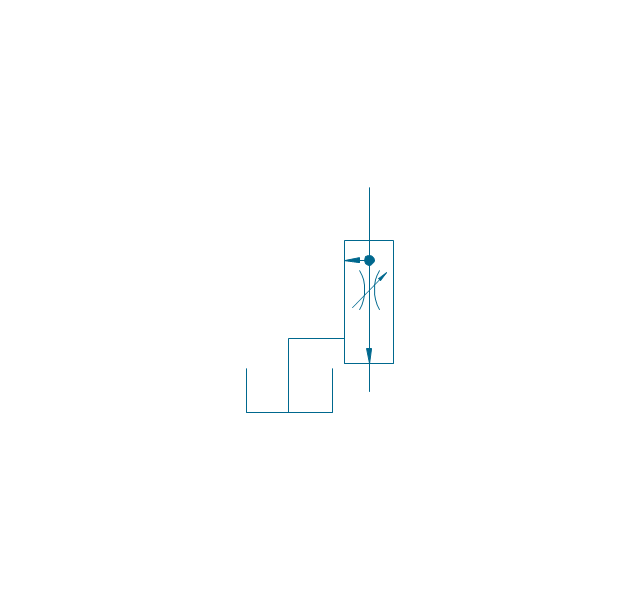
One-way restrictor, enclosed
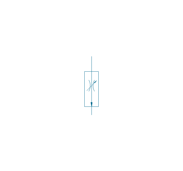
Flow control, series flow
Flow control, temperature compensated
Flow control, bypass flow
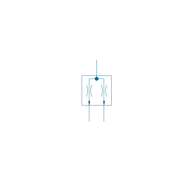
Flow divider
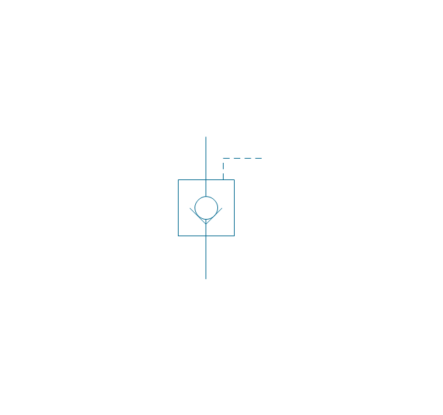
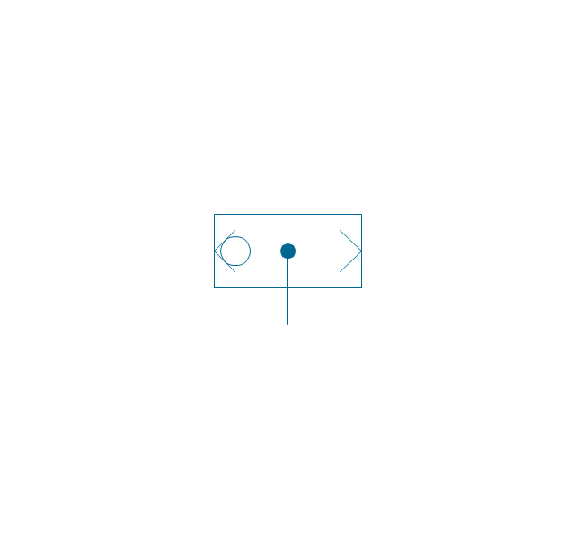
Non-return, pilot controlled
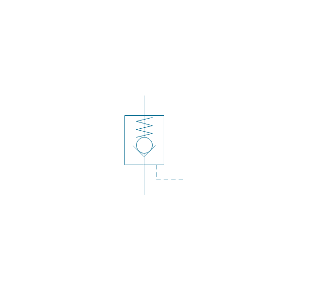
Non-return, pilot contr., spring
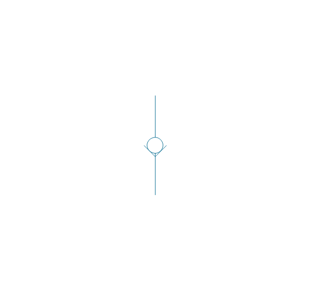
Non-return, free
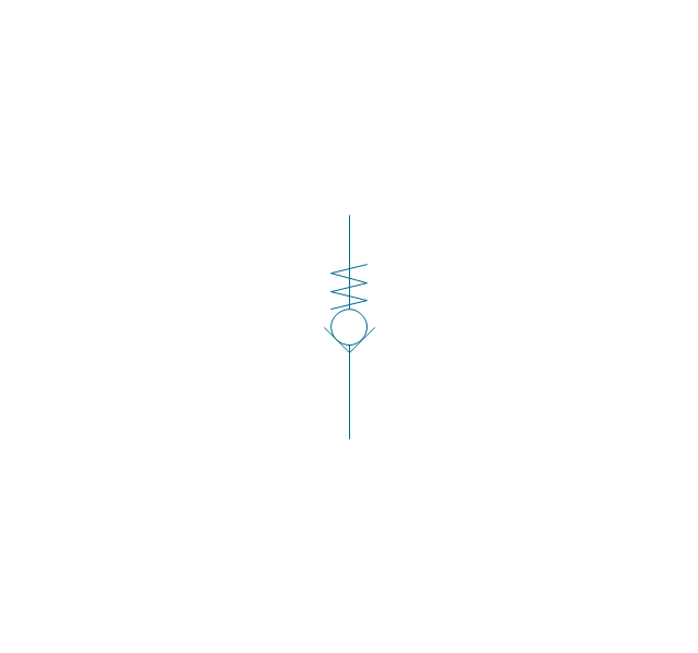
Non-return, spring loaded
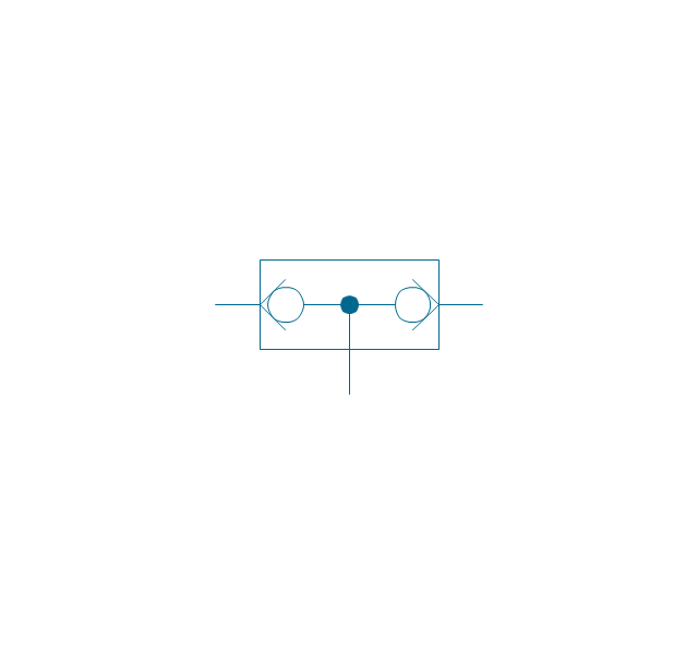
Coupling (connect.), 1 valve
,-1-valve-fluid-power-valves---vector-stencils-library.png--diagram-flowchart-example.png)
Coupling (connect.), both valves
,-both-valves-fluid-power-valves---vector-stencils-library.png--diagram-flowchart-example.png)
Coupling (connect.), no valves
,-no-valves-fluid-power-valves---vector-stencils-library.png--diagram-flowchart-example.png)
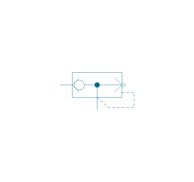
Coupling (connect.), 1 valve, encl.
,-1-valve,-encl.-fluid-power-valves---vector-stencils-library.png--diagram-flowchart-example.png)
Coupling (connect.), both valves, encl.
,-both-valves,-encl.-fluid-power-valves---vector-stencils-library.png--diagram-flowchart-example.png)
Coupling (connect.), no valves, encl.
,-no-valves,-encl.-fluid-power-valves---vector-stencils-library.png--diagram-flowchart-example.png)
Coupling (discon.), 1 valve
,-1-valve-fluid-power-valves---vector-stencils-library.png--diagram-flowchart-example.png)
Coupling (discon.), both valves
,-both-valves-fluid-power-valves---vector-stencils-library.png--diagram-flowchart-example.png)
Coupling (discon.), no valves
,-no-valves-fluid-power-valves---vector-stencils-library.png--diagram-flowchart-example.png)
Coupling (discon.), 1 valve, encl.
,-1-valve,-encl.-fluid-power-valves---vector-stencils-library.png--diagram-flowchart-example.png)
Coupling (discon.), both valves, encl.
,-both-valves,-encl.-fluid-power-valves---vector-stencils-library.png--diagram-flowchart-example.png)
Coupling (discon.), no valves, encl.
,-no-valves,-encl.-fluid-power-valves---vector-stencils-library.png--diagram-flowchart-example.png)
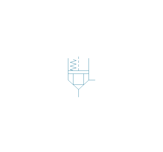
Shuttle valve
Priority shuttle valve
Quick exhaust
Cartridge valve
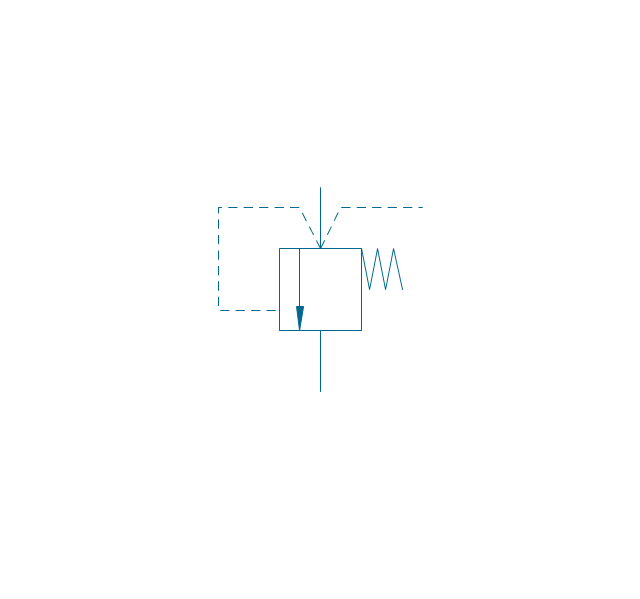
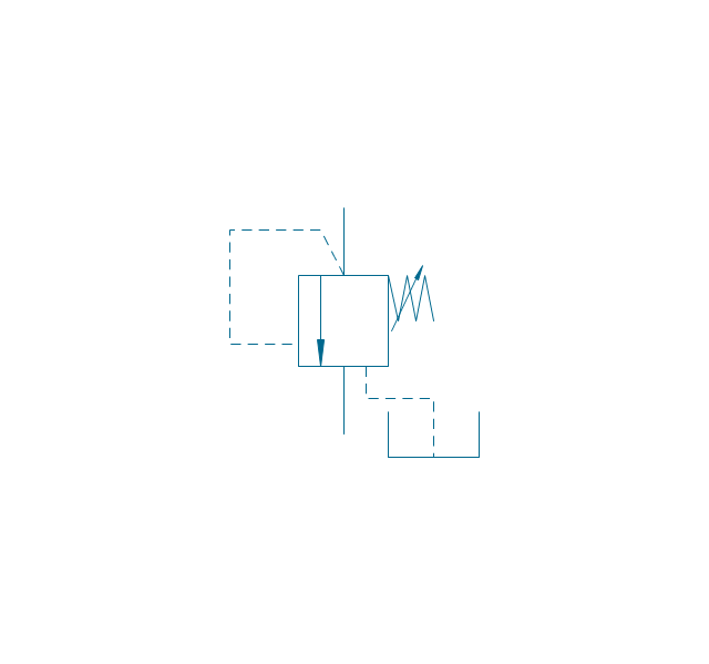
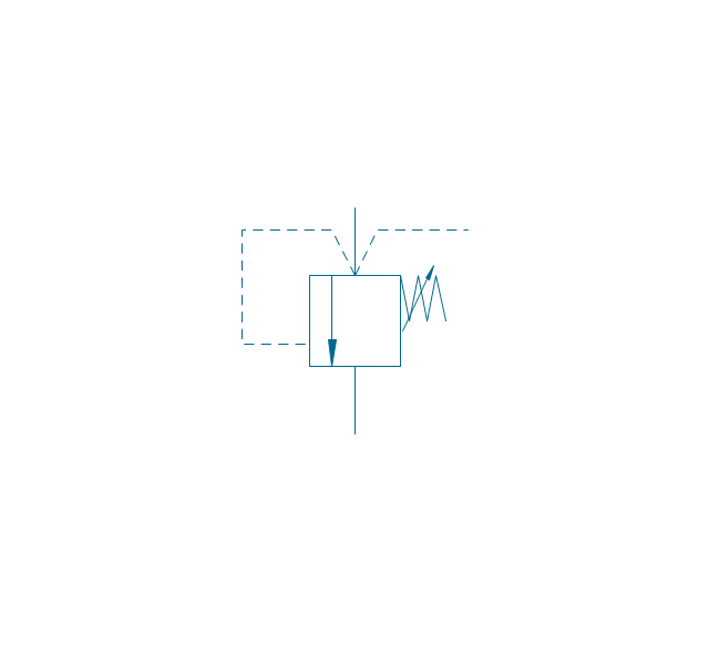
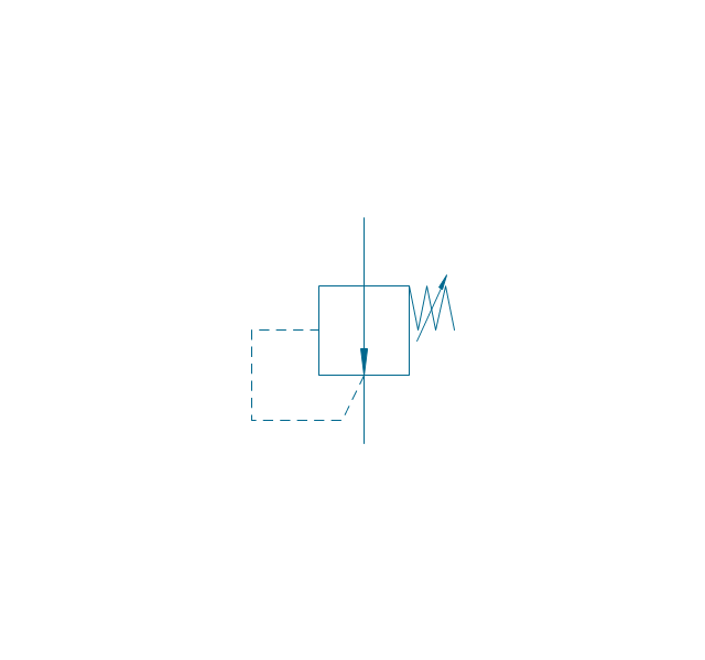
Pressure relief
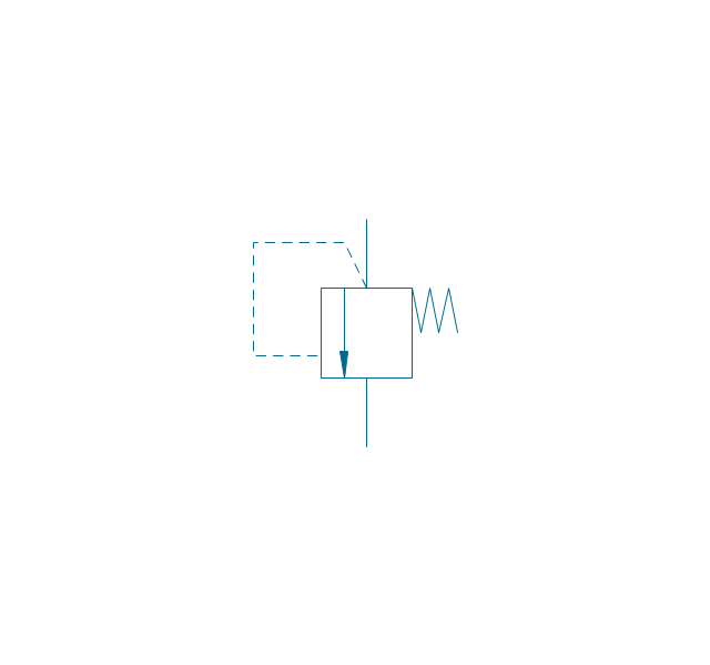
Pressure relief, drain
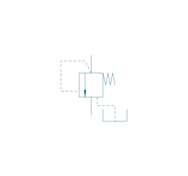
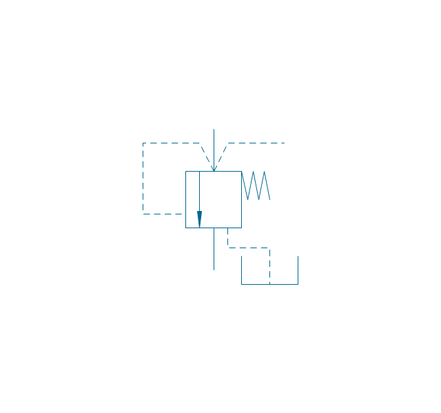
Pressure relief, vent port
Pressure relief, drain, vent port
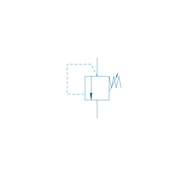
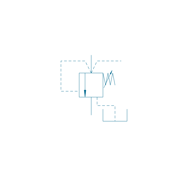
Pressure relief, var.
Pressure relief, var., drain
Pressure relief, var., vent port
Pressure relief, var., drain, vent port
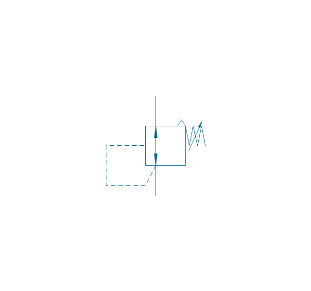
Pressure relief 2
Pressure reducing, 1 stage
Pressure reducing, 2 stage
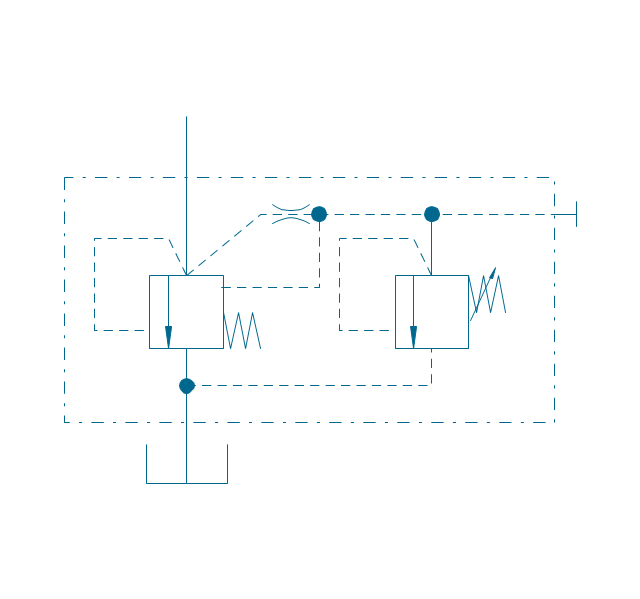
Pressure reducing, relief
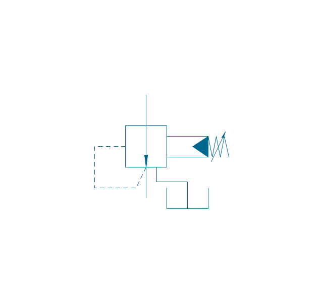
Pressure relief (E)
-fluid-power-valves---vector-stencils-library.png--diagram-flowchart-example.png)
Mechanical Engineering

Technical Drawing Software

UML State Machine Diagram.Design Elements

HelpDesk
How to Create a Mechanical Diagram

CAD Drawing Software for Making Mechanic Diagram and Electrical Diagram Architectural Designs


Value stream with ConceptDraw DIAGRAM

- Mechanical Drawing Symbols | Design elements - Fluid power ...
- Process Flow Diagram | Design elements - Fluid power valves ...
- Design elements - Fluid power valves | Design elements - Valve ...
- Valves Mechanical Assembly Drawing Part By Part
- Mechanical Drawing Symbols | Design elements - Valve assembly ...
- Mechanical Drawing Symbols | Design elements - Valve assembly ...
- Mechanical Drawing Symbols | Design elements - Valve assembly ...
- Control Valve Assembly In Piping Drawing
- Design elements - Valve assembly | Valve assembly - Vector ...
- Mechanical Drawing Symbols | Process Flow Diagram Symbols ...
- Hydraulic schematic | Hydraulic 4-ported 3-position valve template ...
- Mechanical Engineering | Valve assembly - Vector stencils library ...
- Design elements - Valve assembly | Design elements - Fluid power ...
- Ball Valve Assembly Drawing
- Types Of Valves And Symbols
- Mechanical Drawing Symbols | Mechanical Engineering | Design ...
- Pneumatic 4-ported 3-position valve template - Win | Mechanical ...
- Design elements - Valve assembly | Mechanical Engineering ...
- Cylinder Relief Valve Assembly Drawing