 Specification and Description Language (SDL)
For people in the field of systems engineering or system design, working with specification and description language (sdl) and finite state machines (fsm).
This system architecture diagram example was redesigned from the Wikimedia Commons file: SdlArchitecture.JPG. [commons.wikimedia.org/ wiki/ File:SdlArchitecture.JPG]
This file is licensed under the Creative Commons Attribution-Share Alike 3.0 Unported license. [creativecommons.org/ licenses/ by-sa/ 3.0/ deed.en]
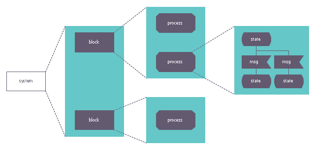
"Architecture.
An SDL system is made of functional blocks and each block can be further decomposed in sub-blocks. The lowest level block is composed of one or several process described as finite state machines." [Specification and Description Language. Wikipedia]
The diagram example "SDL Architecture" was created using the ConceptDraw PRO diagramming and vector drawing software extended with the Specification and Description Language (SDL) solution from the Engineering area of ConceptDraw Solution Park.
This file is licensed under the Creative Commons Attribution-Share Alike 3.0 Unported license. [creativecommons.org/ licenses/ by-sa/ 3.0/ deed.en]
"Architecture.
An SDL system is made of functional blocks and each block can be further decomposed in sub-blocks. The lowest level block is composed of one or several process described as finite state machines." [Specification and Description Language. Wikipedia]
The diagram example "SDL Architecture" was created using the ConceptDraw PRO diagramming and vector drawing software extended with the Specification and Description Language (SDL) solution from the Engineering area of ConceptDraw Solution Park.
System architecture
HelpDesk
How to Create a SDL Diagram
 diagram")
FSM — Finite-state Machine

System Design

Introduction to Cloud Computing Architecture

 AWS Architecture Diagrams
AWS Architecture Diagrams with powerful drawing tools and numerous predesigned Amazon icons and AWS simple icons is the best for creation the AWS Architecture Diagrams, describing the use of Amazon Web Services or Amazon Cloud Services, their application for development and implementation the systems running on the AWS infrastructure. The multifarious samples give you the good understanding of AWS platform, its structure, services, resources and features, wide opportunities, advantages and benefits from their use; solution’s templates are essential and helpful when designing, description and implementing the AWS infrastructure-based systems. Use them in technical documentation, advertising and marketing materials, in specifications, presentation slides, whitepapers, datasheets, posters, etc.
 Enterprise Architecture Diagrams
Enterprise Architecture Diagrams solution extends ConceptDraw PRO software with templates, samples and library of vector stencils for drawing the diagrams of enterprise architecture models.
Types of Flowcharts


ER Diagram for Cloud Computing

 Azure Architecture
Azure Architecture solution bundles into one handy tool everything you need to create effective Azure Architecture diagrams. It adds the extra value to versatile ConceptDraw PRO software and extends the users capabilities with comprehensive collection of Microsoft Azure themed graphics, logos, preset templates, wide array of predesigned vector symbols that covers the subjects such as Azure management, Azure storage, and Azure services, amongst others, and allow you to illustrate Azure Architecture diagrams at any degree of complexity, to present visually your Azure cloud system architecture with professional style, to design Azure cloud topology, to document Windows Azure Architecture and Azure Cloud System Architecture, to visualize the great abilities and work of Microsoft Azure Cloud System and Azure services.
 IDEF Business Process Diagrams
Use the IDEF Business Process Diagrams solution to create effective database designs and object-oriented designs, following the integration definition methodology.
 Interactive Voice Response Diagrams
Interactive Voice Response Diagrams solution extends ConceptDraw PRO v10 software with samples, templates and libraries of ready-to-use vector stencils that help create Interactive Voice Response (IVR) diagrams illustrating in details a work of interactive voice response system, the IVR system’s logical and physical structure, Voice-over-Internet Protocol (VoIP) diagrams, and Action VoIP diagrams with representing voice actions on them, to visualize how the computers interact with callers through voice recognition and dual-tone multi-frequency signaling (DTMF) keypad inputs.
UML Composite Structure Diagram


Mechanical Design Software

- Specification and Description Language (SDL) | AWS Architecture ...
- Azure Architecture | Cafe and Restaurant Floor Plans | Specification ...
- Specification and Description Language (SDL) | How to Create a ...
- Specification and Description Language example | Specification and ...
- SDL — Systems Engineering | Specification and Description ...
- Finite State Machine | Specification and Description Language (SDL ...
- Example Of Example Of System Description Language
- SDL Diagram | SDL — Systems Engineering | Specification and ...
- Process Flowchart | Specification and Description Language (SDL ...
- Specification and Description Language (SDL) | Types of Flowcharts ...
- Design Description Language
- Specification and Description Language (SDL) | Finite State ...
- System Design Description
- Azure Architecture | Network Diagram Software LAN Network ...
- Specification and Description Language (SDL) | Personal area (PAN ...
- Types of Flowcharts | Specification and Description Language (SDL ...
- Types of Flowcharts | Android GUI | Specification and Description ...
- Security and Access Plans | Specification and Description Language ...
- Specification and Description Language (SDL) | Entity-Relationship ...