Personal area (PAN) networks. Computer and Network Examples
 networks")

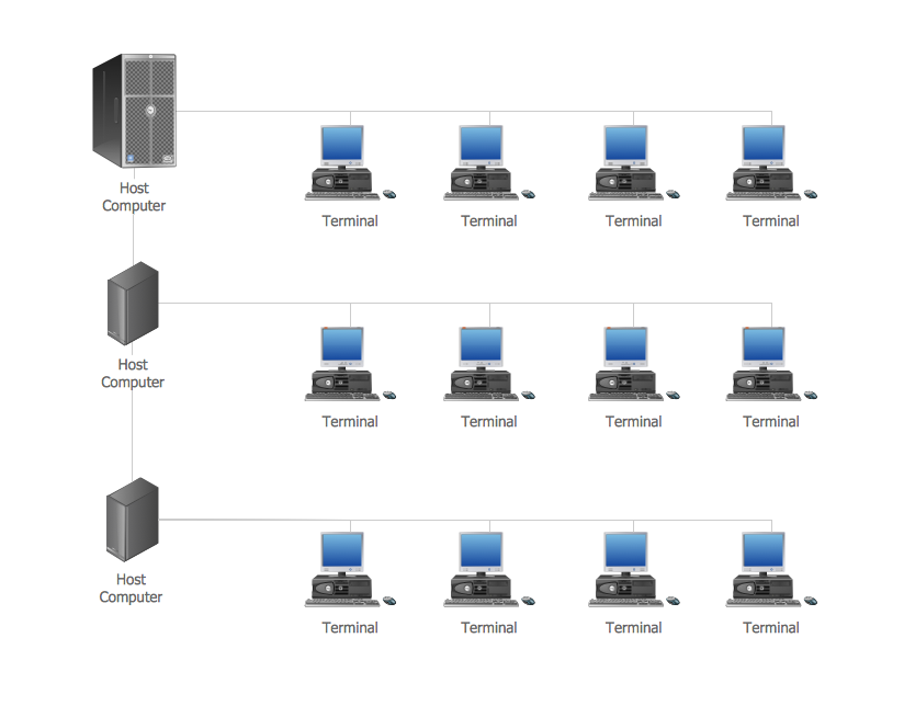
Network Topologies


Computer Network. Computer and Network Examples
Cisco Network Templates

Design Element: Computer and Network for Network Diagrams
.png)
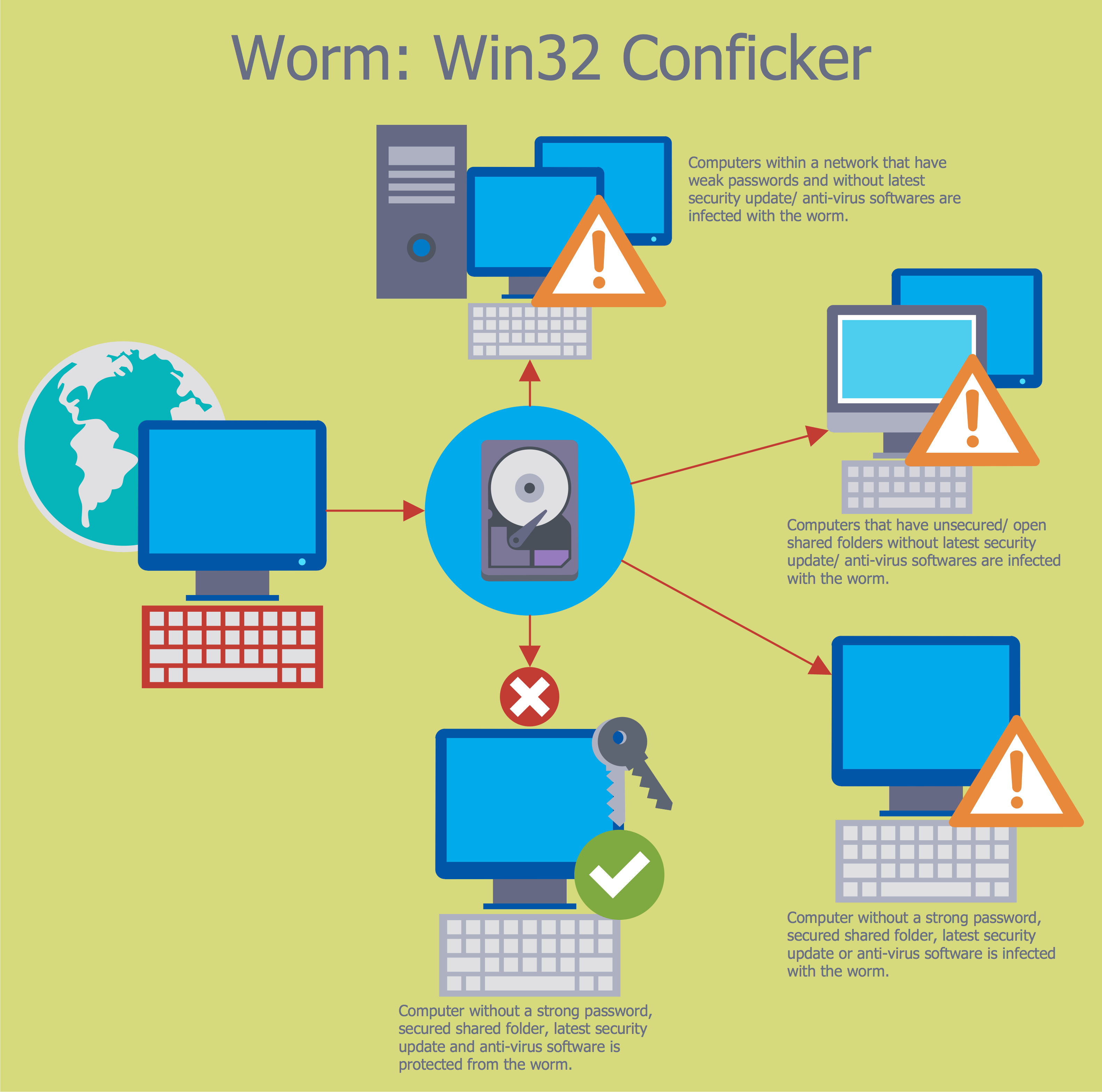
Network Security Tips
Network Gateway Router

Think. Act. Accomplish.
Project — Working With Costs

Think and act effectively
Entity-Relationship Diagram (ERD) with ConceptDraw DIAGRAM


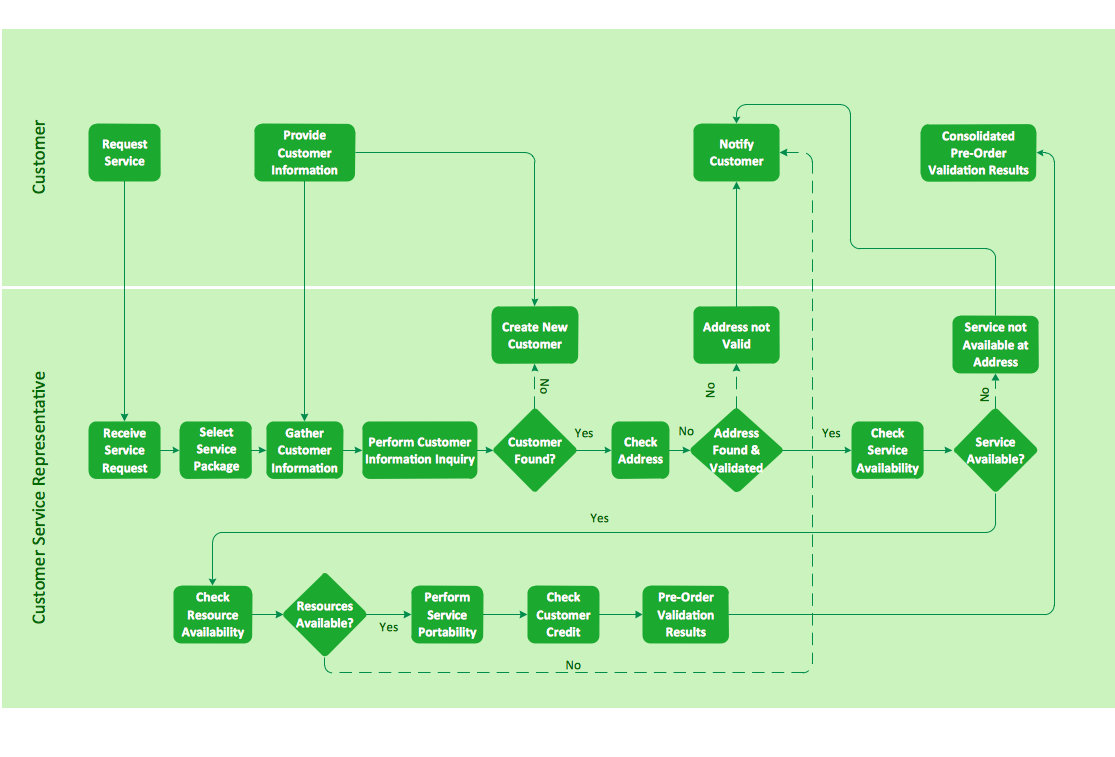
Cross-functional flowchart landscape, U.S. units
Electrical Symbols, Electrical Diagram Symbols

- Advantages And Disadvantages Of Personal Area Network Pdf
- Advantages Of Personal Area Network
- Advantages And Disadvantages Of Personal Area Network Article
- Easy Hints For Advantages And Disadvantages Of Pan Network
- Hybrid Network Topology | Star Network Topology | Campus Area ...
- Network Topologies Advantages And Disadvantages And The
- Advantages Of Network Diagram
- Fully Connected Network Topology Diagram | Network Topologies ...
- Fully Connected Network Topology Diagram | Star Network ...
- Network Security Tips | Network Topologies | Local network area ...
- Full Connected Network Advantages And Disadvantages
- Advantage And Disadvantage Of Structure System Analaysis Desining
- Fully Connected Network Topology Diagram | Hybrid Network ...
- Personal area ( PAN ) networks . Computer and Network Examples ...
- Personal area ( PAN ) networks . Computer and Network Examples ...
- Using Both Wired and Wireless Connections | Personal area ( PAN ...
- Star Network Topology | Personal area ( PAN ) networks . Computer ...
- Long-range Wi-Fi network diagram | Personal area ( PAN ) networks ...
- Personal area ( PAN ) networks . Computer and Network Examples ...
- Wireless Network Diagram Examples | Personal area ( PAN ...