This example of automated payroll management system UML activity diagram was created on the base of figure on the webpage "Automated payroll management system" from ethelmandane.wikispaces.com.
"In the Philippines and in other foreign countries the government has a trend to embrace automation for process efficiency. One of the processes that are being automated is the payroll process. Payroll is the total amount required to pay workers and employees during a week, month or other period.
One of the government offices that desires to automate their payroll system is the NSO Camarines Sur which is located 2nd Floor MMCN Building, Panganiban Avenue, Naga City. The National Statistics Office (NSO) envisions to be recognized as a world-class provider of statistical and civil registration products and services and lives with its mission to produces and provides quality statistical and civil registration products and services. ...
The project seeks to create an Information System Plan for an Automated Payroll Management System. ...
The creation of the Information System Plan will benefit the accounting section of the organization. Specifically it is significant to:
1. Administrative Assistants. It will help to lessen time and effort in preparing and computing the salary of the employee.
2. NSO. It will help the organization to be more productive and efficient."
[ethelmandane.wikispaces.com/ ]
This file is licensed under a Creative Commons Attribution Share-Alike 3.0 License. [creativecommons.org/ licenses/ by-sa/ 3.0/ ]
This UML activity diagram example modeling the automated payroll management system using automated teller machine (ATM) was created using the ConceptDraw PRO diagramming and vector drawing software extended with the ATM UML Diagrams solution from the Software Development area of ConceptDraw Solution Park.
UML activity diagram of automated payroll management system using ATM

 Flowcharts
The Flowcharts solution for ConceptDraw PRO is a comprehensive set of examples and samples in several varied color themes for professionals that need to represent graphically a process. Solution value is added by the basic flow chart template and shapes' libraries of flowchart notation. ConceptDraw PRO flow chart creator lets one depict the processes of any complexity and length, as well as design the Flowchart either vertically or horizontally.
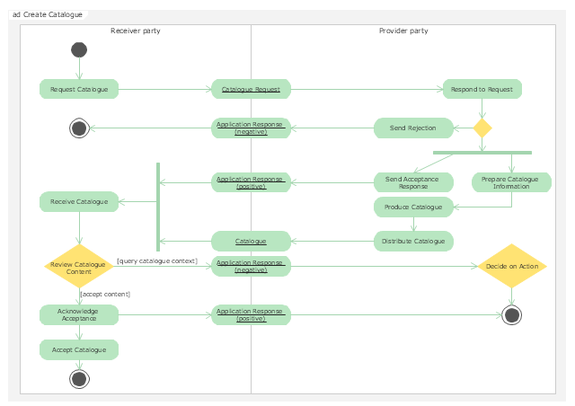
"Activity diagrams are graphical representations of workflows of stepwise activities and actions with support for choice, iteration and concurrency. In the Unified Modeling Language, activity diagrams are intended to model both computational and organisational processes (i.e. workflows). Activity diagrams show the overall flow of control." [Activity diagram. Wikipedia]
The UML activity diagram example "Catalogue creation process" was created using the ConceptDraw PRO diagramming and vector drawing software extended with the Rapid UML solution from the Software Development area of ConceptDraw Solution Park.
The UML activity diagram example "Catalogue creation process" was created using the ConceptDraw PRO diagramming and vector drawing software extended with the Rapid UML solution from the Software Development area of ConceptDraw Solution Park.
UML activity diagram
UML Deployment Diagram Example - ATM System UML diagrams

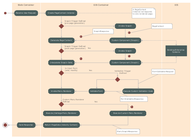
"Microsoft Management Console is a component of Windows 2000 and its successors that provides system administrators and advanced users an interface for configuring and monitoring the system.
Snap-ins and consoles.
The management console can host Component Object Model components called snap-ins. Most of Microsoft's administration tools are implemented as MMC snap-ins. Third parties can also implement their own snap-ins using the MMC's application programming interfaces published on the Microsoft Developer Network's web site." [Microsoft Management Console. Wikipedia]
The UML activity diagram example "Snap in process" was created using the ConceptDraw PRO diagramming and vector drawing software extended with the Rapid UML solution from the Software Development area of ConceptDraw Solution Park.
UML activity diagram
Swim Lane Flowchart Symbols

Swim Lane Diagrams

Booch OOD Diagram

Types of Flowchart - Overview


Accounting Flowchart Symbols

UML Class Diagram Example - Medical Shop

 ATM UML Diagrams
The ATM UML Diagrams solution lets you create ATM solutions and UML examples. Use ConceptDraw PRO as a UML diagram creator to visualize a banking system.
Cross Functional Diagram

Influence Diagram

Basic Flowchart Symbols and Meaning


- Automated payroll management system UML activity diagram | UML ...
- Automated payroll management system UML activity diagram
- Automated payroll management system UML activity diagram
- UML Activity Diagram | Diagramming Software for Design UML ...
- Automated payroll management system UML activity diagram | Swim ...
- Automated payroll management system UML activity diagram ...
- Automated payroll management system UML activity diagram | ATM ...
- UML activity diagram - Ticket processing system | Automated payroll ...
- UML activity diagram - Cash withdrawal from ATM | UML Activity ...
- UML activity diagram (swimlanes) - Template | Automated payroll ...
- Automated payroll management system UML activity diagram | Flow ...
- Automated payroll management system UML activity diagram
- Activity Diagram Swimlane Accounting
- Activity Diagram For Employee Payroll Bank System
- Activity Diagram For Atm Process Using Swimlane
- UML activity diagram (swimlanes) - Template | Swim Lane Flowchart ...
- UML Activity Diagram
- UML Activity Diagram | Automated payroll management system UML ...
- Automated payroll management system UML activity diagram | Basic ...
- UML activity diagram - Cash withdrawal from ATM | UML Activity ...