Electrical Symbols — Switches and Relays

Mechanical Drawing Software

 Mechanical Engineering
This solution extends ConceptDraw DIAGRAM.9 mechanical drawing software (or later) with samples of mechanical drawing symbols, templates and libraries of design elements, for help when drafting mechanical engineering drawings, or parts, assembly, pneumatic,
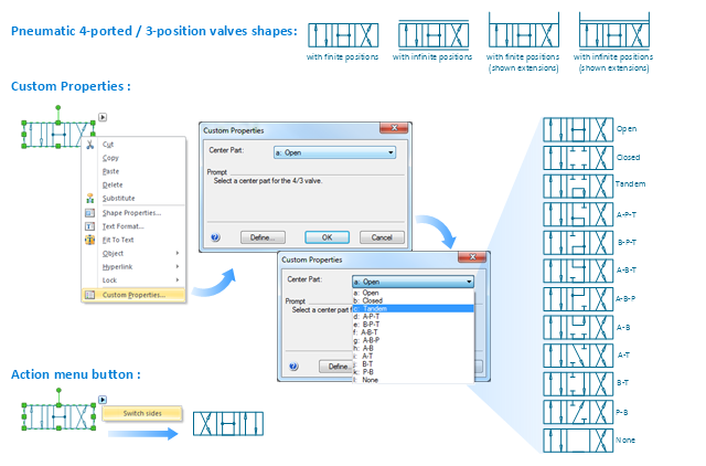
"An air-operated valve is a type of power operated valve that uses air pressure against a piston or diaphragm to produce linear or circular movement to operate a valve. Types are 2-way, 3-way and 4-way. The 2 way air-operated valves can be either normally closed or normally opened." [Air-operated valve. Wikipedia]
The Windows template "Pneumatic 4-ported 3-position valve" for the ConceptDraw PRO diagramming and vector drawing software is included in the Mechanical Engineering solution from the Engineering area of ConceptDraw Solution Park.
www.conceptdraw.com/ solution-park/ engineering-mechanical
The Windows template "Pneumatic 4-ported 3-position valve" for the ConceptDraw PRO diagramming and vector drawing software is included in the Mechanical Engineering solution from the Engineering area of ConceptDraw Solution Park.
www.conceptdraw.com/ solution-park/ engineering-mechanical
Pneumatic directional control valve
The vector stencils library "Switches and relays" contains 58 symbols of electrical contacts, switches, relays, circuit breakers, selectors, connectors, disconnect devices, switching circuits, current regulators, and thermostats for electrical devices.
Use these shapes for drawing electrical diagrams in the ConceptDraw PRO diagramming and vector drawing software extended with the Electrical Engineering solution from the Engineering area of ConceptDraw Solution Park.
www.conceptdraw.com/ solution-park/ engineering-electrical
Use these shapes for drawing electrical diagrams in the ConceptDraw PRO diagramming and vector drawing software extended with the Electrical Engineering solution from the Engineering area of ConceptDraw Solution Park.
www.conceptdraw.com/ solution-park/ engineering-electrical
SPST

SPDT

DPST

DPDT

Make contact

Break contact

Two way contact

Passing make-contact

Spring return

Stay put

Limit switch

Circuit breaker

Spring return 2

Spring return 3

Limit switch n/o

Limit switch n/c

2 position switch

3 position switch

4 position switch

Manual switch

Pushbutton make

Pushbutton break

Pushbutton 2-circuit

Selector switch

Shorting selector

Proximity limit switch

Time delay make

Time delay break

Time delay make 2

Time delay break 2

Safety interlock

Flow actuated

Liquid level actuated

Liquid level actuated 2

Gas flow actuated

Pressure actuated

Temperature actuated

Thermostat

Temperature switch

Inertia switch

Mercury switch

Mercury switch 2

Fuse

Switch disconnector

Isolator

Change-over contact

Relay contacts

Relay coil

Pilot light

Pilot light, push-to-test

Relay, alternating-current

Relay, magnetically polarized

Relay, slow-operate

Relay, slow-release

Relay

Relay, high speed

Relay, mechanically latched

Relay, permanent

Local area network (LAN). Computer and Network Examples


Electrical Symbols, Electrical Diagram Symbols

Electrical Symbols — Composite Assemblies

Flowchart Components

Home Electrical Plan

- Electrical Symbols, Electrical Diagram Symbols | Vacuum Pressure ...
- Vector Diagram For Pneumatics
- Position Symbol Diagram
- Mechanical Engineering | How to Create a Mechanical Diagram ...
- Directional control valve | Pneumatic 5-ported 3 - position valve ...
- Pneumatic 5-ported 3 - position valve template - Mac | Mechanical ...
- Mechanical Drawing Symbols | Pneumatic 5-ported 3 - position valve ...
- Design elements - Pneumatic pumps and motors | Pneumatic 5 ...
- Mechanical Engineering | Pneumatic 5-ported 3 - position valve ...
- Design elements - Ports and Flows | Design elements - UML ...