Network Printer


Office Floor Plans

Network Diagram Software
Network Drawing Software

Interior Design. Office Layout Plan Design Element


Network Diagram Software Enterprise Private Network
ConceptDraw Arrows10 Technology
Cisco WAN. Cisco icons, shapes, stencils and symbols

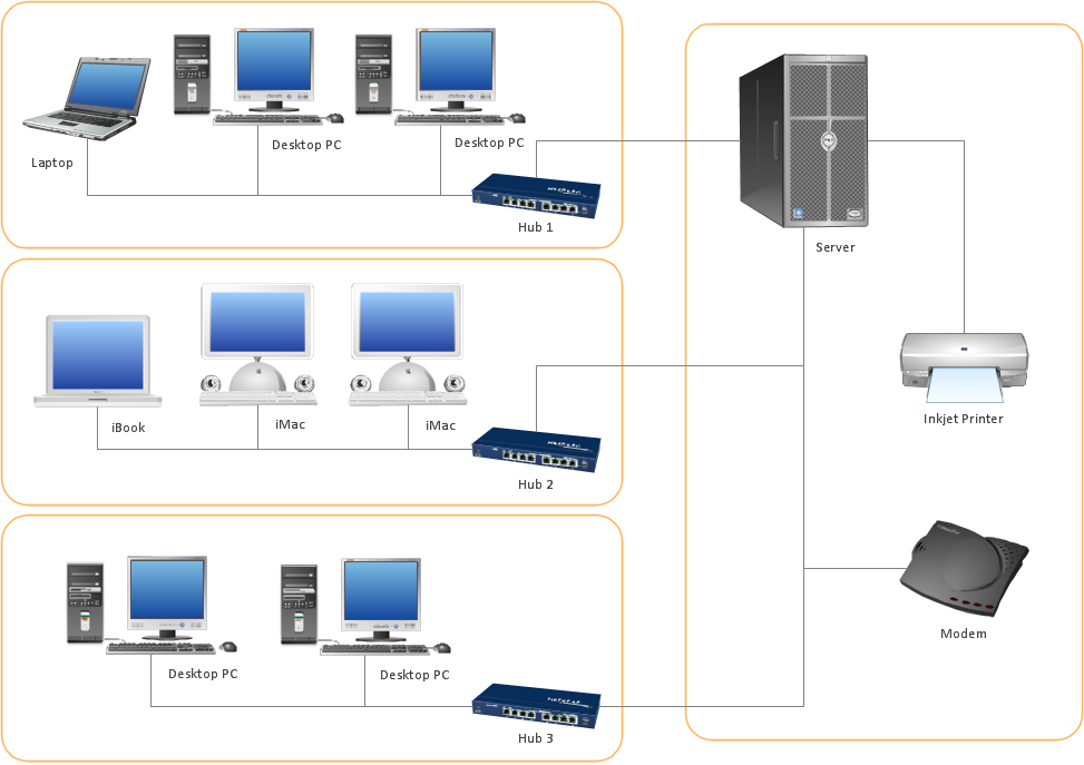
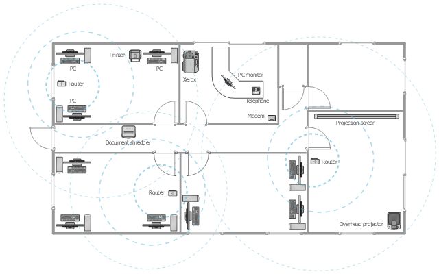
This office floor plan sample depicts the equipment layout of wireless computer network.
"A wireless local area network (WLAN) links two or more devices using some wireless distribution method (typically spread-spectrum or OFDM radio), and usually providing a connection through an access point to the wider Internet. This gives users the ability to move around within a local coverage area and still be connected to the network. Most modern WLANs are based on IEEE 802.11 standards, marketed under the Wi-Fi brand name." [Wireless LAN. Wikipedia]
The equipment layout example "Office wireless network plan" was created using the ConceptDraw DIAGRAM diagramming and vector drawing software extended with the Office Layout Plans solution from the Building Plans area of ConceptDraw Solution Park.
Equipment layout
"The Ethernet physical layer is the physical layer component of the Ethernet family of computer network standards.
The Ethernet physical layer evolved over a considerable time span and encompasses quite a few physical media interfaces and several magnitudes of speed. The speed ranges from 1 Mbit/ s to 100 Gbit/ s, while the physical medium can range from bulky coaxial cable to twisted pair and optical fiber. In general, network protocol stack software will work similarly on all physical layers.
10-gigabit Ethernet was already used in both enterprise and carrier networks by 2007, with 40 Gbit/ s and 100 Gbit/ s Ethernet ratified. ...
Many Ethernet adapters and switch ports support multiple speeds, using autonegotiation to set the speed and duplex for the best values supported by both connected devices. If auto-negotiation fails, a multiple-speed device will sense the speed used by its partner, but will assume half-duplex. A 10/ 100 Ethernet port supports 10BASE-T and 100BASE-TX. A 10/ 100/ 1000 Ethernet port supports 10BASE-T, 100BASE-TX, and 1000BASE-T." [Ethernet physical layer. Wikipedia]
The LAN equipment and cabling layout floorplan example "Ethernet local area network layout floor plan" was created using the ConceptDraw PRO diagramming and vector drawing software extended with the Network Layout Floor Plans solution from the Computer and Networks area of ConceptDraw Solution Park.
Ethernet LAN layout floorplan

Network Diagrams for Bandwidth Management
How to Build Cloud Computing Diagram Principal Cloud Manufacturing

Network Diagramming Software for Design Computer and Network Diagrams
_Win_Mac.png)
- Network Printer | Interior Design Office Layout Plan Design Element ...
- Network Printer | Building Drawing Software for Design Office Layout ...
- Interior Design Office Layout Plan Design Element | Office wireless ...
- Reflected Ceiling Plans | Network Printer | Reflected Ceiling Plan ...
- Network Printer | | | Printer
- Network Printer | Network Layout | Using Both Wired and Wireless ...
- Network Printer | Cisco Products Additional. Cisco icons, shapes ...
- Network Printer | Design Element: Computer and Network for ...
- Ethernet local area network layout floor plan | Network Diagram ...
- Reflected Ceiling Plans | Network Printer | Fishbone Diagram | How ...
- Diagram Of Connecting Printer To Desktop Mac
- How To Connect Printer Between Two Lan By Using Network ...
- Home Design Software | How To use House Design Software ...
- Restaurant Floor Plan Software | Symbol for Pool Table for Floor ...
- Network Printer | Physical LAN topology diagram | Using Both Wired ...
- Office Layout Plans | Office Floor Plans | Network Printer | Drawing ...
- Network Floor Plan
- Ethernet local area network layout floor plan | Network layout ...
- | Computer and Networks Area | Calendar Printer
- Network Printer | Network diagrams with ConceptDraw PRO ...